
An Apparatus for Reclaiming Foundry Sand

a technology for reclaiming foundry sand and equipment, which is applied in the direction of gas current separation, manufacturing tools, and mold making equipment, etc., and can solve the problem of requiring regular cleaning

Active Publication Date: 2015-07-02
SINTOKOGIO LTD
View PDF3 Cites 7 Cited by
  • Summary
  • Abstract
  • Description
  • Claims
  • Application Information

AI Technical Summary

Benefits of technology

The present invention is about an apparatus for reclaiming foundry sand. It includes a tank for fluidization, a dust hood, and a bed of fluidized sand. The tank has a unique design with alternating covering and flooring members that create slits for air. This design prevents clogging and allows for efficient air supply. The apparatus also has a front sectional view for easy understanding. The technical effects of the invention include improved fluidization of sand and prevention of clogging.

Problems solved by technology

Thus a problem occurs whereby a regular cleaning is required.

Method used


Image

  • An Apparatus for Reclaiming Foundry Sand
  • An Apparatus for Reclaiming Foundry Sand
  • An Apparatus for Reclaiming Foundry Sand

Examples


Embodiment Construction

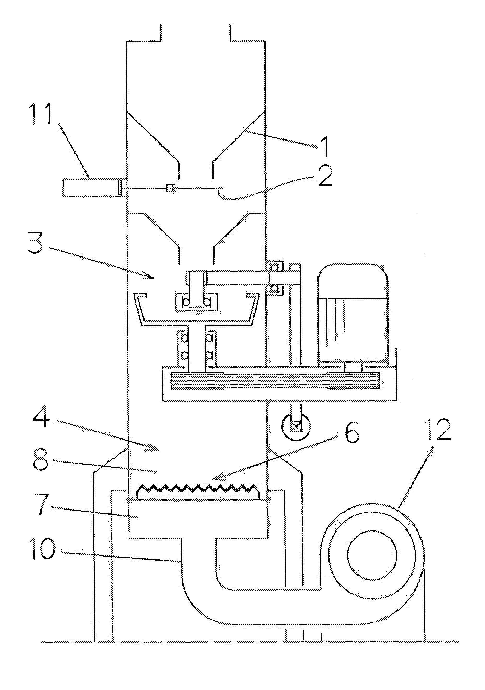
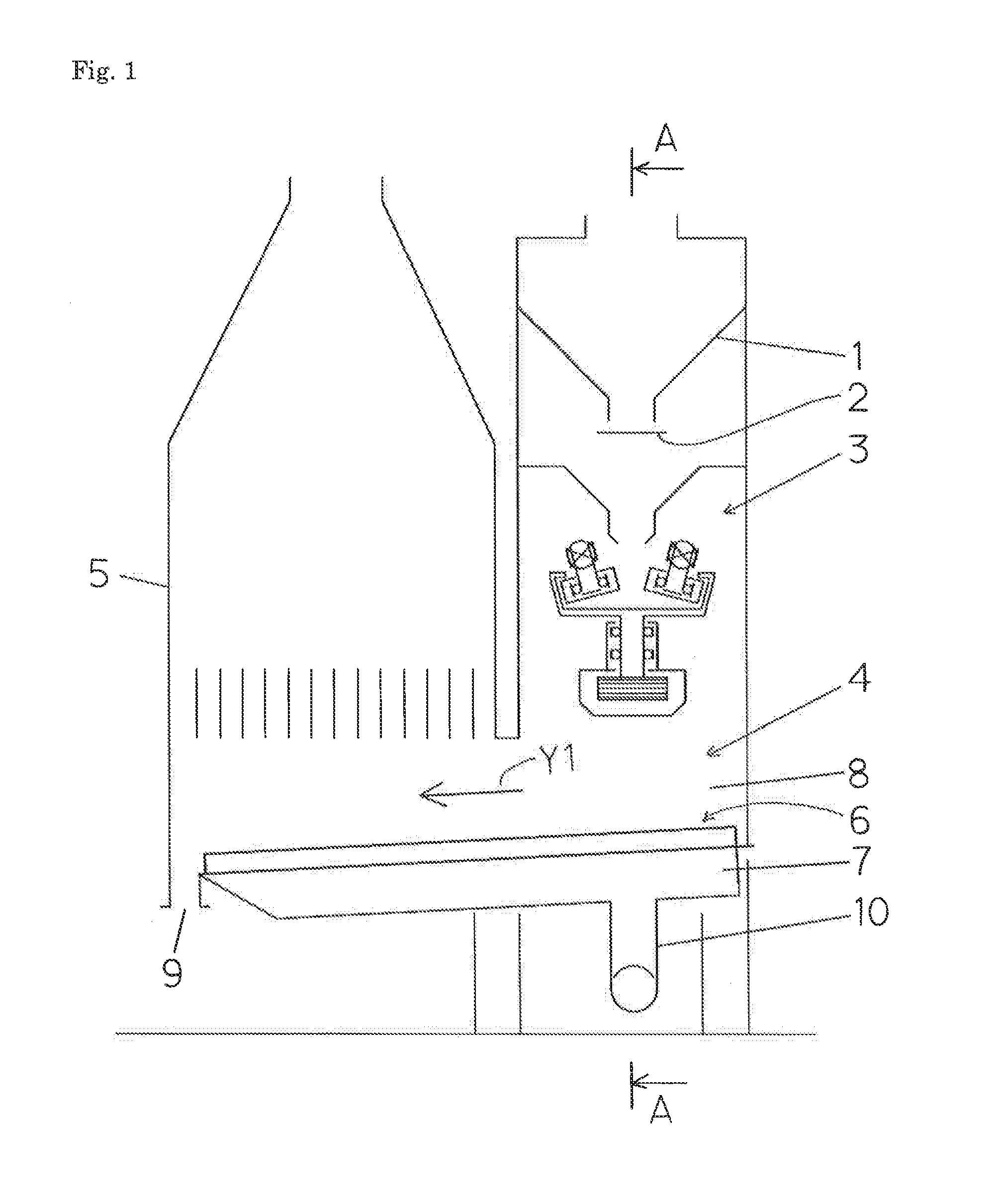
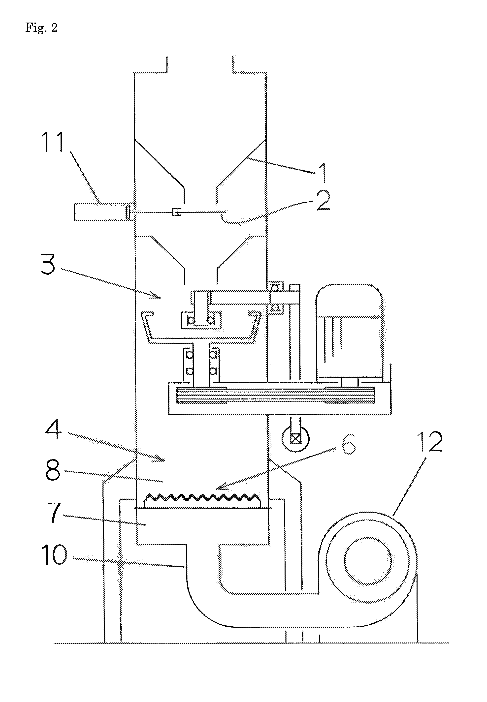
[0021]Below, an embodiment of the present invention is discussed with reference to the drawings. By this embodiment, reclaiming self-hardening foundry sand that has been used in a process for self-hardening molding by using alkali phenol is discussed as an example. First, the entire structure of an apparatus for reclaiming self-hardening foundry sand is discussed. In FIG. 1 the number “1” denotes a hopper for returned foundry sand that stores the self-hardening foundry sand that has been used and returned. A gate 2 is provided at the lower end of the hopper for returned foundry sand 1 so that the gate 2 is opened and closed by a cylinder 11 for opening and closing a gate (see FIG. 2).

[0022]The hopper 1 for returned foundry sand is at its lower portion connected to a tank 3 for reclaiming the foundry sand. In the tank 3 for reclaiming the foundry sand the particles of the self-hardening foundry sand that has been fed scrape each other so as to strip off binders on the surfaces of the...


PUM


Abstract

To provide an apparatus for reclaiming foundry sand that has a fluidized bed that prevents slits from being clogged. The apparatus comprises a tank (3) for reclaiming the foundry sand, a tank (4) for fluidization, an upper portion of which in an upstream side is connected to a bottom of the tank for reclaiming the foundry sand, the tank for fluidization transporting the reclaimed foundry sand and fine powder that drop from the tank for reclaiming the foundry sand, a dust hood (5), and a lower portion of which communicates with an upper portion of the tank for fluidization in a downstream side, the dust hood collecting the fine powder in the tank for fluidization, wherein a fluidized bed (6) in the tank for fluidization has a plurality of inverted. V-shaped covering members (13) and a plurality of V-shaped flooring members (14), wherein the inverted V-shaped covering members and the V-shaped flooring members are horizontally and alternately provided so that the inverted V-shaped covering members are at any point above a vertically corresponding point of the V-shaped flooring members, and wherein gaps between end portions of the inverted V-shaped covering members and end portions of the V-shaped flooring members are formed as inclined slits (15) for supplying air.

Description

TECHNICAL FIELD[0001]The present invention relates to an apparatus for reclaiming foundry sand by stripping the binders on the surfaces of the particles of the foundry sand that is used (for example, self-hardening foundry sand).BACKGROUND ART[0002]In conventional apparatuses for reclaiming foundry sand, the following process has been known to remove dust that is generated when reclaiming the foundry sand: forming a fluidized layer by blowing air into the foundry sand that includes dust; blowing the foundry sand and dust up and into a dust hood for classifying the sand and dust; and classifying them by the differences in the rates at which they settle (for example, Japanese Patent No. 3329757). As a fluidized bed for forming the fluidized layer the structure as in FIG. 6 has been used: That is, slits 101 for upwardly blowing air are formed in a plate with slits 100. If the particles of the sand that have piled around the slits 101 drop through the slits 101 when air stops being blow...

Claims


Application Information

Patent Timeline
IPC IPC(8): B22C5/10B02C23/20B02C23/10
CPCB22C5/10B02C23/20B02C23/10B03B4/06B07B4/08
Inventor AOKI, YUKINORI
Owner SINTOKOGIO LTD
Learn More