Vehicle body vibration-damping control device

a control device and vehicle body technology, applied in vehicle position/course/altitude control, process and machine control, instruments, etc., can solve the problem that the device cannot be expected to have an adequate effect in the vehicle, and achieve the effect of increasing the actual drive torque response and reducing the non-operation region

Active Publication Date: 2015-07-02
NISSAN MOTOR CO LTD
View PDF2 Cites 3 Cited by
  • Summary
  • Abstract
  • Description
  • Claims
  • Application Information

AI Technical Summary

Benefits of technology

[0010]Specifically, a region where the positive or negative attribute of the correction torque value is reversed is a region where the actuator response is delayed, or a dead zone region. Taking note of this region and amplifying the absolute value of the correction torque in the region where the positive or negative attribute is reversed—that is, increasing the amount of correction for either a plus or minus correction torque value—expands the operation region where the actuator operates with respect to the applied drive torque command value. This has the effect of decreasing the non-operation region of the actuator in association with this expansion of the operation region of the actuator, and increasing the actual drive torque response to the drive torque command value applied to the actuator.
[0011]As a result, a targeted effect for damping the vehicle body vibration can be achieved regardless of the responsiveness of an actuator for controlling the drive torque.

Problems solved by technology

For this reason, the conventional device has had the problem that the device cannot be expected to have an adequate effect in a vehicle that has low response to control command values, such as an engine-driven vehicle.

Method used


Image

  • Vehicle body vibration-damping control device
  • Vehicle body vibration-damping control device
  • Vehicle body vibration-damping control device

Examples


example 1

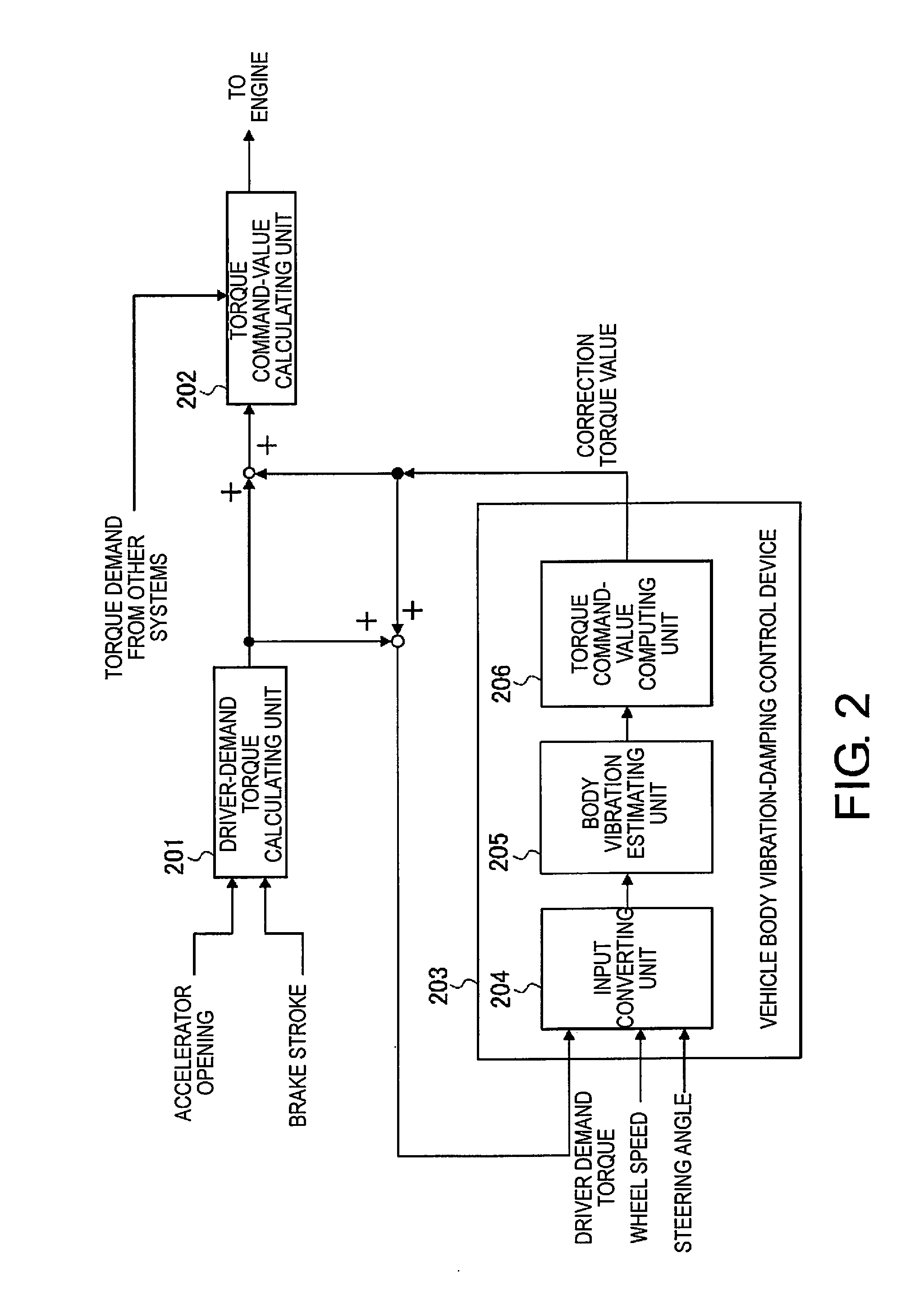
[0035]First, the configuration will be described. The configuration in Example 1 will be described divided into “Overall system configuration,”“Internal configuration of engine control module,”“Configuration of input converting unit of vehicle body vibration-damping control device,”“Configuration of body vibration estimating unit of vehicle body vibration-damping control device,” and “Configuration of torque command-value computing unit of vehicle body vibration-damping control device.”

[0036]Overall System Configuration

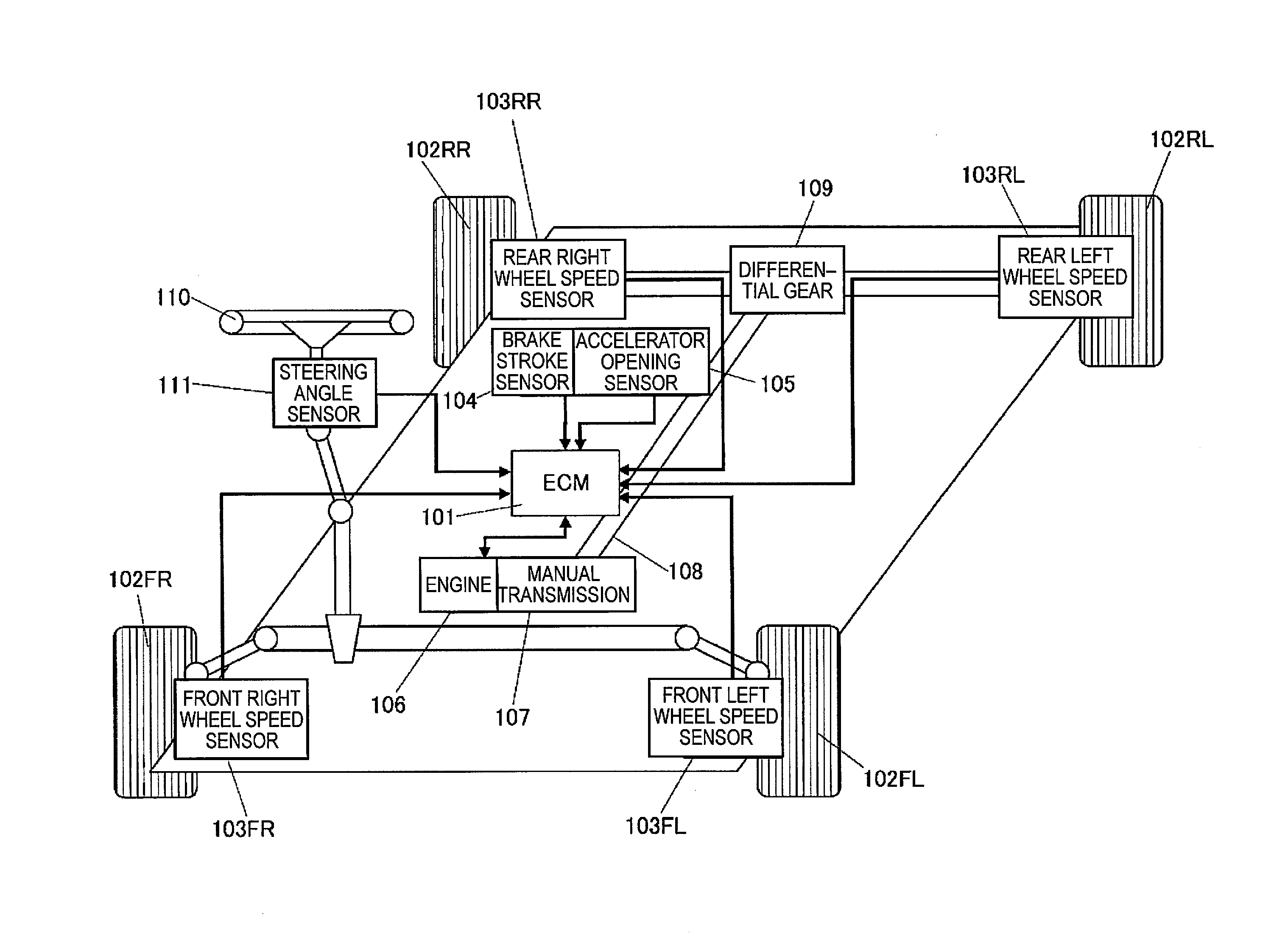
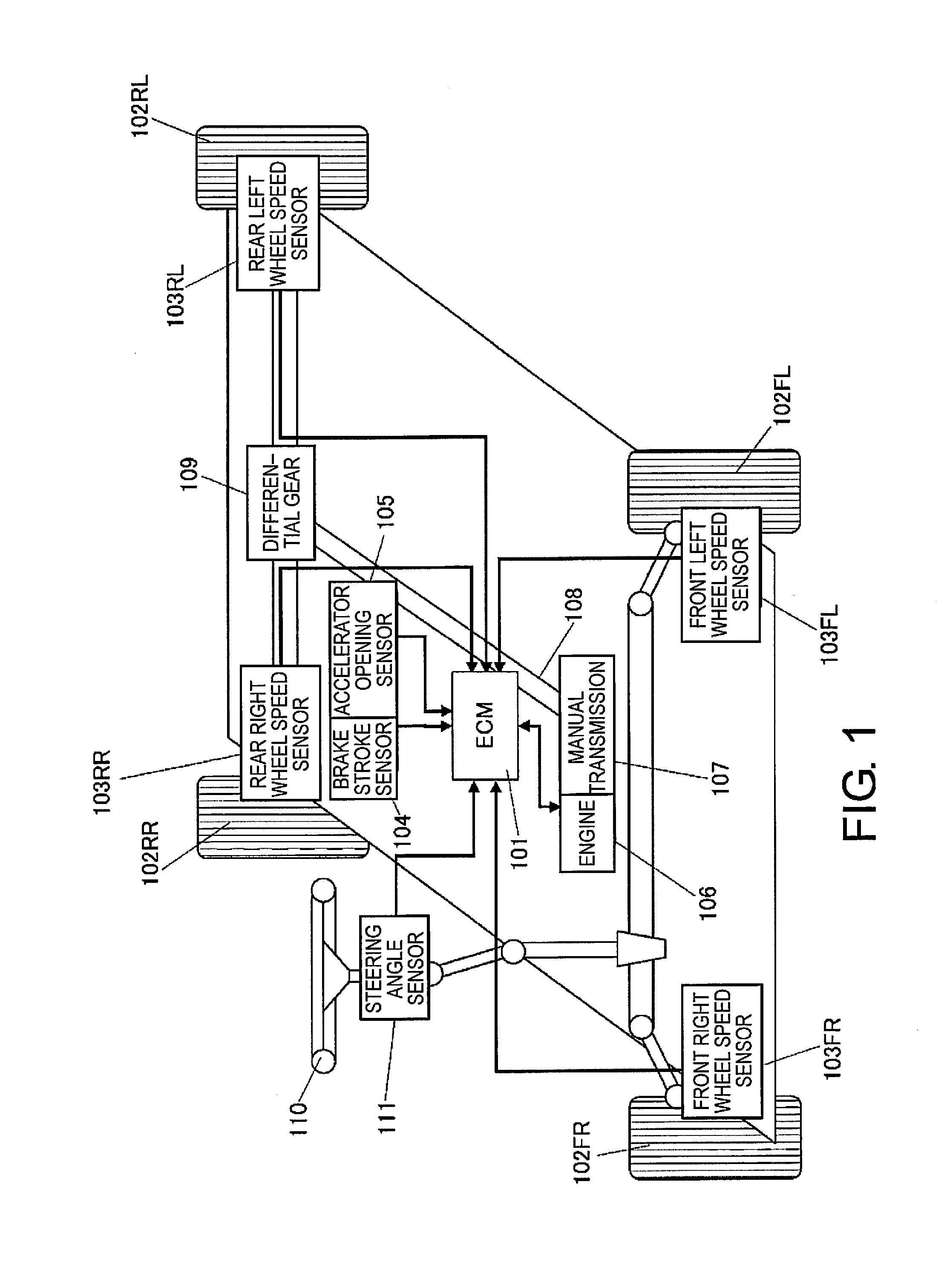
[0037]FIG. 1 is a schematic block diagram of the overall system of an engine-driven vehicle to which the vehicle body vibration-damping control device of Example 1 is applied. The overall system configuration will be described hereinafter based on FIG. 1. “Vehicle body vibration-damping control” refers to control having a function for restraining vehicle body vibration by optimally controlling the drive torque produced by the actuator of a vehicle (in Example 1, an en...


PUM


Abstract

An object of the vehicle body vibration-damping control device according to the present invention is to achieve a targeted effect for damping the vehicle body vibration regardless of the responsiveness of an actuator for controlling the drive torque.
The vehicle body vibration-damping control device has a body vibration estimating unit (205) for estimating a sprung mass behavior of a vehicle body based on input information during travel, and a torque command-value computing unit (206) for computing a correction torque value for correcting a drive torque command value applied to an engine (106) when the sprung mass behavior is controlled. The torque command-value computing unit (206) has regulator and tuning units (308, 309, 310) for calculating the correction torque value based on the result of estimating the sprung mass behavior, and a nonlinear gain amplifying unit (313) for amplifying the absolute value of the correction torque when in a region where the positive or negative attribute of the calculated correction torque value is reversed, and using the amplified value to correct the drive torque command value.

Description

CROSS-REFERENCE TO RELATED APPLICATIONS[0001]This application is a U.S. National stage application of International Application No. PCT / JP2013 / 053403, filed Feb. 5, 2013, which claims priority to Japanese Patent Application No. 2012-031645 filed in Japan on Feb. 16, 2012. The entire disclosure of Japanese Patent Application No. 2012-031645 is hereby incorporated herein by reference.BACKGROUND[0002]1. Field of the Invention[0003]The present invention relates to a vehicle body vibration-damping control device for controlling drive torque to restrain the sprung mass behavior of a vehicle body estimated based on input information during travel.[0004]2. Background Information[0005]In the past, a vehicle body vibration-damping control device has been known in which drive torque is controlled to correct the drive torque so as to stabilize sprung mass behavior (e.g., refer to Japanese Laid-Open Patent Application No. 2006-264628).SUMMARY[0006]This conventional vehicle body vibration-damping...

Claims


Application Information

Patent Timeline
Patent Type & Authority Applications(United States)
IPC IPC(8): B60W30/045B60W40/10B60W10/22B60W30/04B60W10/06
CPCB60W30/045B60W30/04B60W10/06B60W2030/043B60W40/10B60W2030/041B60W10/22B60W50/0097B60W50/0098B60W10/04B60W30/18B60W2050/0012B60W2510/22B60W2720/16B60W30/20B60W2050/0024B60W2540/10B60W2540/12B60W2540/18B60W2710/0666Y02T10/84
Inventor SHIOZAWA, YUUKIKAWAGUCHI, SHOJIKOBAYASHI, YOSUKE
Owner NISSAN MOTOR CO LTD
Why Eureka
Try Eureka