Athletic Protective Mouthpiece and Lip Shield Apparatus

Active Publication Date: 2015-07-30
ZENTS SHAWN ALAN
2 Cites 15 Cited by

AI-Extracted Technical Summary

Problems solved by technology

For example in U.S. Pat. No. 2,589,504 is a protector for the lips and teeth, however this mouth protector only allows the front teeth to contact with the top and bottom of it's airway structure, putting all the stress on the front teeth during bite, thus leaving the middle and back rows of an athlete's teeth suspended and unprotected.
As a result of this me...

Benefits of technology

[0011]The Athletic Protective Mouthpiece and Lip Shield Apparatus of the present invention overcomes the problems associated with prior art. The main objectives of present invention is to provide an improved protective mouthpiece for teeth and lips without any breathing restrictions is as follows: 1) to provide an improved large airway or Air Channel structure by which a protective Lip Shield and mouthpiece connects to said Air Channel structure, and a short strap with a foot attachment structure descends from said Lip Shield to attach to the helmet's chinstrap. 2) to improve the comfort of the mouth by suspending front teeth behind the opening of the Air Channel's internal structure thus removing st...

Abstract

This invention is an athletic protective mouthpiece and lip shield apparatus used in contact sports and is designed to attach to a helmet's chin strap. The mouthpiece, Air Channel, and Lip Shield structures are particularly designed to comfortably protect both upper and lower jaw of the athlete while removing unwanted impact stress from the front teeth (Incisors) and placing such stress to the stronger Cuspid and Molars regions of the athlete's dentures. This invention solves the problems of airflow restriction and impact stress of the front teeth from other athletic mouthpieces by removing the position of the Incisors from atop the breathing orifice to behind said orifice, whereby providing an improved larger non-condensing airway for the passing of unrestricted airflow. The apparatus is designed to pivot and operate by way of an attachment strap affixed to the Lip shield and fitted into an opening on the helmet's chin strap.

Application Domain

Technology Topic

Image

  • Athletic Protective Mouthpiece and Lip Shield Apparatus
  • Athletic Protective Mouthpiece and Lip Shield Apparatus
  • Athletic Protective Mouthpiece and Lip Shield Apparatus

Examples

  • Experimental program(1)

Example

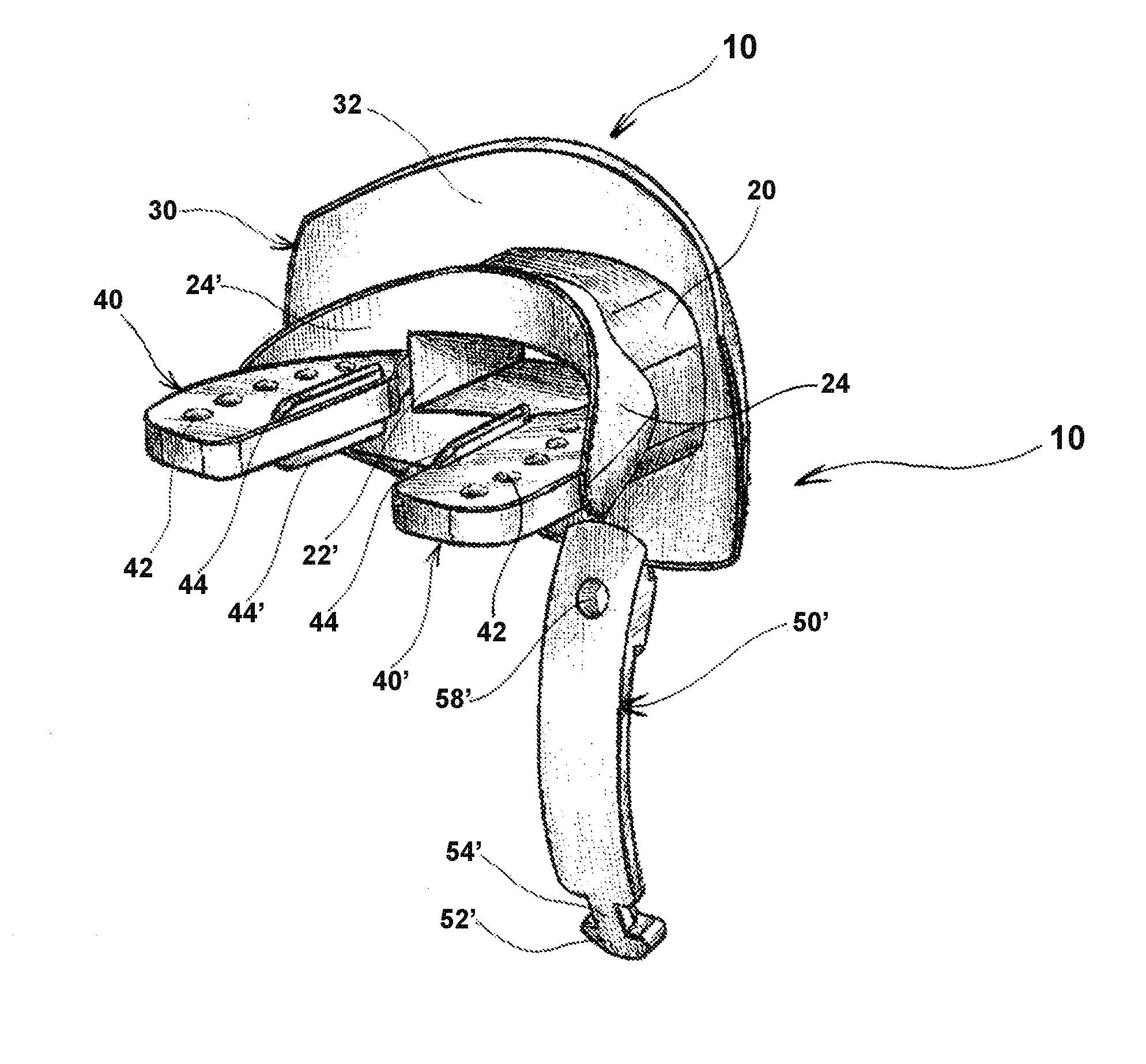
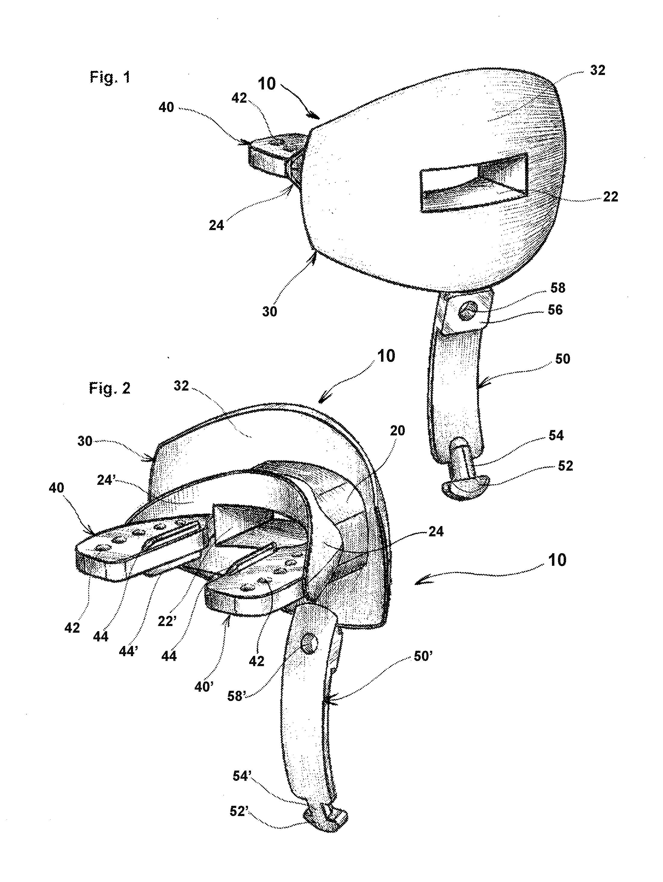
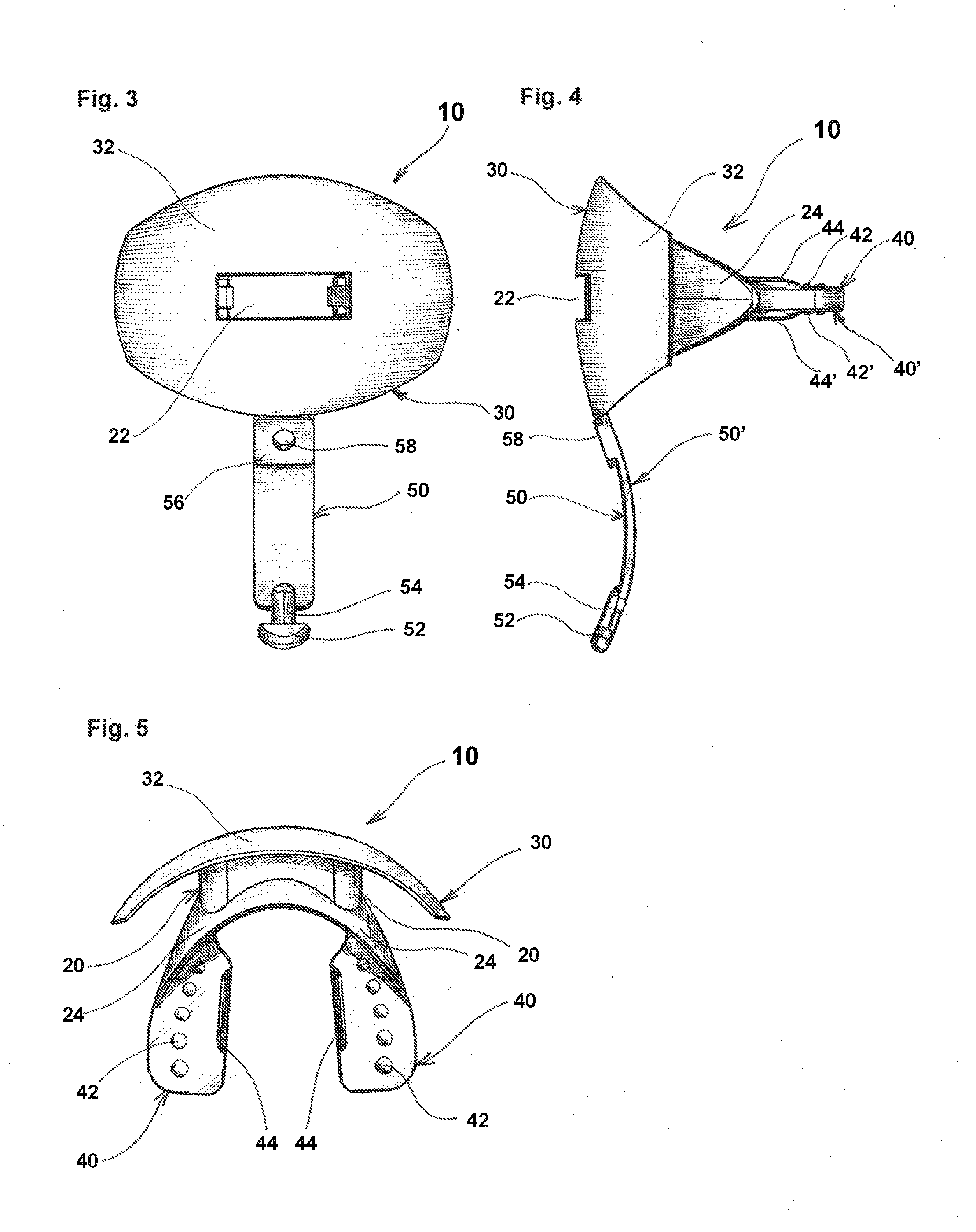
[0025]Overview: In FIG. 1 a preferred form of the athletic protective mouthpiece and lip shield embodying the present invention, generally designated 10, includes a circular midsection or Air Channel structure 20, connected to a protective Lip Shield 30, similarly, connected to the Air Channel structure, extends two protective mouthpiece Tooth Pads 40, with a short strap leg extending downward 50 that will connect and pivot P with the helmet's chin strap, as is shown in FIG. 9; the athletic protective Mouthpiece and Lip Shield 10 should be constructed or molded, preferably, from a firm but flexible FDA approved compounding material.
[0026]Structures: Referring now in detail to the drawings of the preferred embodiment of the mouthpiece 10, as best shown in FIGS. 1-8 as constructed or more particularly molded around the Air Channel Structure 20 containing a singular large breathing orifice 22, in which the preferred shape of this orifice is rectangular in design, but not limited to said shape. This orifice originates and follows the curvature of the front of the Lip Shield 30, and continues inward surrounded by the circular Air Channel structure 20 of FIG. 2, which the athlete's lips contact and rest upon when in use by a player, as best illustrated in FIG. 9, FIG. 11 and FIG. 12. additionally, part of the Air Channel's structure is a protective lip flange structure 24 which helps to protect the front teeth and gums from the rear side of said lip flange structure 24′, as well as support and stabilize the mouthpiece's Tooth Pads 40 as they connect and extend outward from said Air Channel, as represented in FIG. 2, FIG. 5 and FIG. 8. finally, the thickness of the Air Channel should be enough that it would not restrict airflow in anyway when an athlete's lips create downward pressure while in use, as shown in FIG. 9, FIG. 11 and FIG. 12.
[0027]The Lip Shield structure 30 curves convexly around the athlete's mouth and lips protecting the anatomy of the Orbicularis Oris muscle from direct contact, as shown in FIG. 11, additionally, the Lip Shield 30 curves slightly longitudinally 32 to conform to the tooth cylinder of the skull, as best demonstrated in FIG. 11, FIG. 4, FIG. 7; the preferred shape of the Shield 30 is generally oval, but not limited to said shape, with curved angles at it's left and right outside edges, as might be seen in FIG. 1, FIG. 2, FIG. 4, and FIG. 7, the shield 30 is fairly thin in nature, approximately ⅛″ to ¼″ in thickness, tapering to it's ends FIG. 2. The exterior portion of the Lip Shield 30, as best illustrated in frontal views like examples FIG. 1 and FIG. 3, contains the breathing orifice or Air Channel 22 and at the bottom central point of the shield connects the short extending Strap Leg 50 ending with an attachment foot 52. The interior portion of the shield 30′ covers and wraps around the corners of the mouth 32′ ending below the nostrils and chin areas of the athlete, as shown in FIG. 9, FIG. 11 and FIG. 12. The Lip Shield 30 is the most notable visible attribute of the preferred embodiment of the present invention 10 and should be constructed or more particularly molded with a firm yet flexible cushioning material compounding.
[0028]The preferred embodiment of the present invention 10 constructed around the Air Channel Structure 20 which is connected to a protective Lip Shield 30 wherein a mouthpiece in U-shaped appearance as to correspond to the curvature of the mouth 40 extending outwardly from the outer ends of the rear side of the lip flange 24′ of previously mentioned Air Channel structure 20 with two protective Tooth Pads 40 which contain small round shaped individualized tooth structures 42 for added comfort and impact absorption, but not solely limited to this shaped design, as well as internal tooth ridge structures 44 in which help keep teeth in place and properly aligned while in use, as best shown in FIG. 2, FIG. 5, and FIG. 8. The inventive nature of this mouthpiece's structure 40 and Air Channel structural design 20 is such as to allow the athlete's front teeth to suspend freely, relaxed, and in a protective position, behind the Air Channel lip flange structure 24 thus allowing the middle and back rows of dentures to carry the stress load while contacting the Tooth Pads 40 during competition, as illustrated in FIG. 11. More notably, the front teeth, both top and bottom, fit up to and most likely against the lip flange 24 of the Air Channel, as shown in FIG. 2, FIG. 11 and FIG. 12 as a result, the mouthpiece structure or Tooth Pads 40 should be molded with a more firm than a more flexible compounding material as to not allow the Tooth Pads 40 to contract, when bitten down upon, wherein not allow the front teeth to contact each other. Therefore, it is preferred that the present invention 10 with said mouthpiece structure 40 be represented as a Ready Made or Non-Moldable mouthpiece, as in FIG. 2. However it could be recommended, if more beneficial, to form a moldable structure on top of this more permanent substructure 40 which may allow a more custom fit by the user.
[0029]Methods of attachment: The connective member 50 of the protective Mouthpiece and Lip Shield of the present invention 10 is a short Strap Leg extending from the bottom of the Lip Shield 30 ending with an attachment Foot 52 which is designed to fit into an opening P on the helmet's chin strap, as shown in FIG. 9 and FIG. 10. Within the various views illustrated in the art of the present invention 10 has visualized the preferred embodiment of the attaching Strap Leg mechanism, as represented in FIG. 1, FIG. 2, FIG. 3, FIG. 4, FIG. 6, FIG. 7, and FIG. 8. Including a rectangular component 56 containing a circular opening 58 which is designed to offer alternative attachment methods, if so desired by an athlete, in which another strap or string could be use to attach present invention 10 through the opening 58 to the face mask of the helmet; likewise, component 56 could be used as a looping structure through which the Leg Strap 50 is bent down and around into the chin strap and then back upwardly towards component 58 attaching where the Foot structure 52 could be fitted into and through component 58's opening. The short thin flexible Leg Strap 50 which is represented originating from the bottom of the Lip Shield 30, but not limited to said position, downwardly towards the Chin Strap ending with a small cylindrical structure 54 and attachment Foot 52, the rear side of said structure 50′ is one of being more smooth of surface descending continuously from the rear of the Lip Shield 30 above; thus allowing little friction with user's chin or chin strap, as FIG. 2, FIG. 4, and FIG. 7 will illustrate. The intent of such a method of attachment is create a pivot point P as shown in FIG. 9 in which the present invention 10 will be allowed to most advantageously enter and exit the mouth freely, as further illustrated in FIG. 9, without hindrance or restriction, thus being of great benefit to player not having to switch his or her focus to the apparatus verse concentrating on the game at hand. Conversely, all other mouthpieces and protectors on the market today are design with no straps, meaning to be hand held when exited the mouth, or are constructed for attachment to fit around and hang from the helmet's face mask.
[0030]Method of Manufacture: In the preferred embodiment of the present invention 10 the entire mouthpiece and lip shield is a one piece molding of an elastomer such as rubber or plastic having a Durometer reading of between approximately 55 and 65 with a Shore A hardness. However, it is believed that a Durometer in the range of 40 to 70 will provide an acceptable mouthpiece. A preferred FDA approved compounding material for production, one that is safe in material, firm and flexible in nature for contact, yet comfortable for use by the athlete.
[0031]While the present invention has been described in connection with particular embodiments thereof, it will be understood by those skilled in the art that many changes and modifications may be made without departing from the true spirit and scope of the present invention. Therefore, it is intended by the appended claims to cover all such changes and modifications which come within the true spirit and scope of this invention.
[0032]Having described and illustrated by word and image the preferred embodiment of the present invention,

PUM

no PUM

Description & Claims & Application Information

We can also present the details of the Description, Claims and Application information to help users get a comprehensive understanding of the technical details of the patent, such as background art, summary of invention, brief description of drawings, description of embodiments, and other original content. On the other hand, users can also determine the specific scope of protection of the technology through the list of claims; as well as understand the changes in the life cycle of the technology with the presentation of the patent timeline. Login to view more.

Similar technology patents

Control method of air conditioner and air conditioner

Owner:GD MIDEA AIR-CONDITIONING EQUIP CO LTD +1

Classification and recommendation of technical efficacy words

  • Improve comfort

Treatment of teeth by aligners

InactiveUS20060275731A1Improve comfortReduce treatment time and costImpression capsAdditive manufacturing apparatusDental treatmentsOrthodontics
Owner:ALIGN TECH

Fan

Owner:UNIVERSAL SAFETY RESPONSE +1

Cleaning method and device for indoor heat exchanger of air conditioner

ActiveCN104848738AAchieve high temperature sterilization functionImprove comfortCleaning heat-transfer devicesSpace heating and ventilation safety systemsFrostEngineering
Owner:GREE ELECTRIC APPLIANCES INC
Why Eureka
Try Eureka