Hand tool display hanger

a technology for hanging racks and tools, applied in the field of hand tool display racks, can solve problems such as difficulty in pulling out, and achieve the effects of reducing assembly time and cost, reducing assembly time, and quick assembly

Inactive Publication Date: 2015-07-30
GONG FONG ENTERPRISE
View PDF2 Cites 10 Cited by
  • Summary
  • Abstract
  • Description
  • Claims
  • Application Information

AI Technical Summary

Benefits of technology

[0019]1. The present invention is structurally simple and can be rapidly put together to reduce the time and cost of assembly. Moreover, the hand tool display hanger of the present invention is visually pleasing when in display, which adds to its commercial value.
[0020]2. In the present invention, the second engaging portion, the second blocking portion, and the second stop block of the fixing base are respectively engaged with the first engaging portion, the first stop block, and the first blocking portion of the fixing portion of the hanger body to produce multiple engaging / blocking effects, thereby preventing the fixing base from coming out of the fixing portion.
[0021]3. A hand tool inserted in the insertion hole of the fixing base of the present invention is tightly held against arbitrary removal.

Problems solved by technology

A hand tool whose diameter is larger than the diameter of the insertion hole can be tightly held in the insertion hole and, once so, is difficult to be pulled out.

Method used


Image

  • Hand tool display hanger
  • Hand tool display hanger
  • Hand tool display hanger

Examples


Embodiment Construction

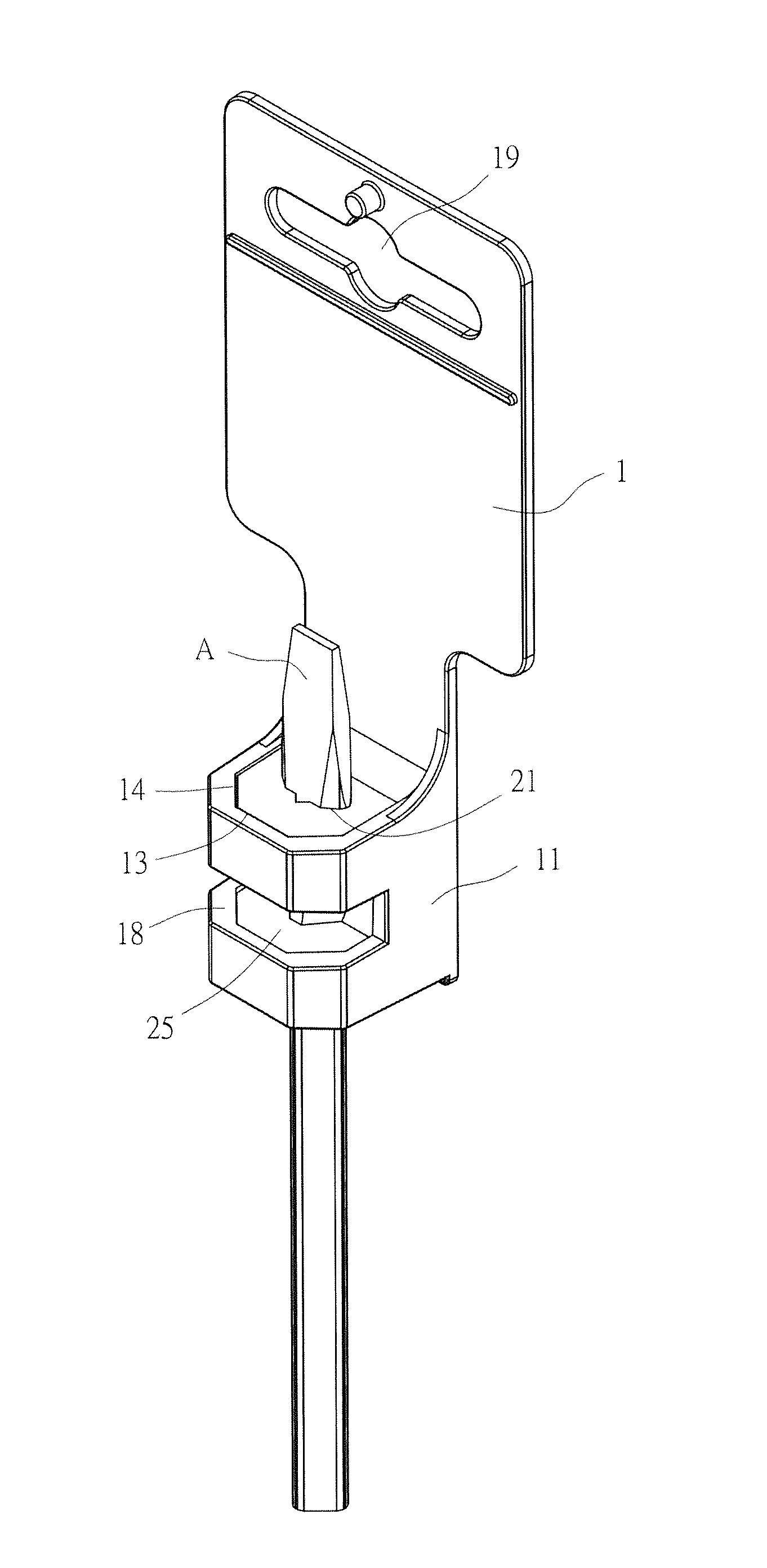
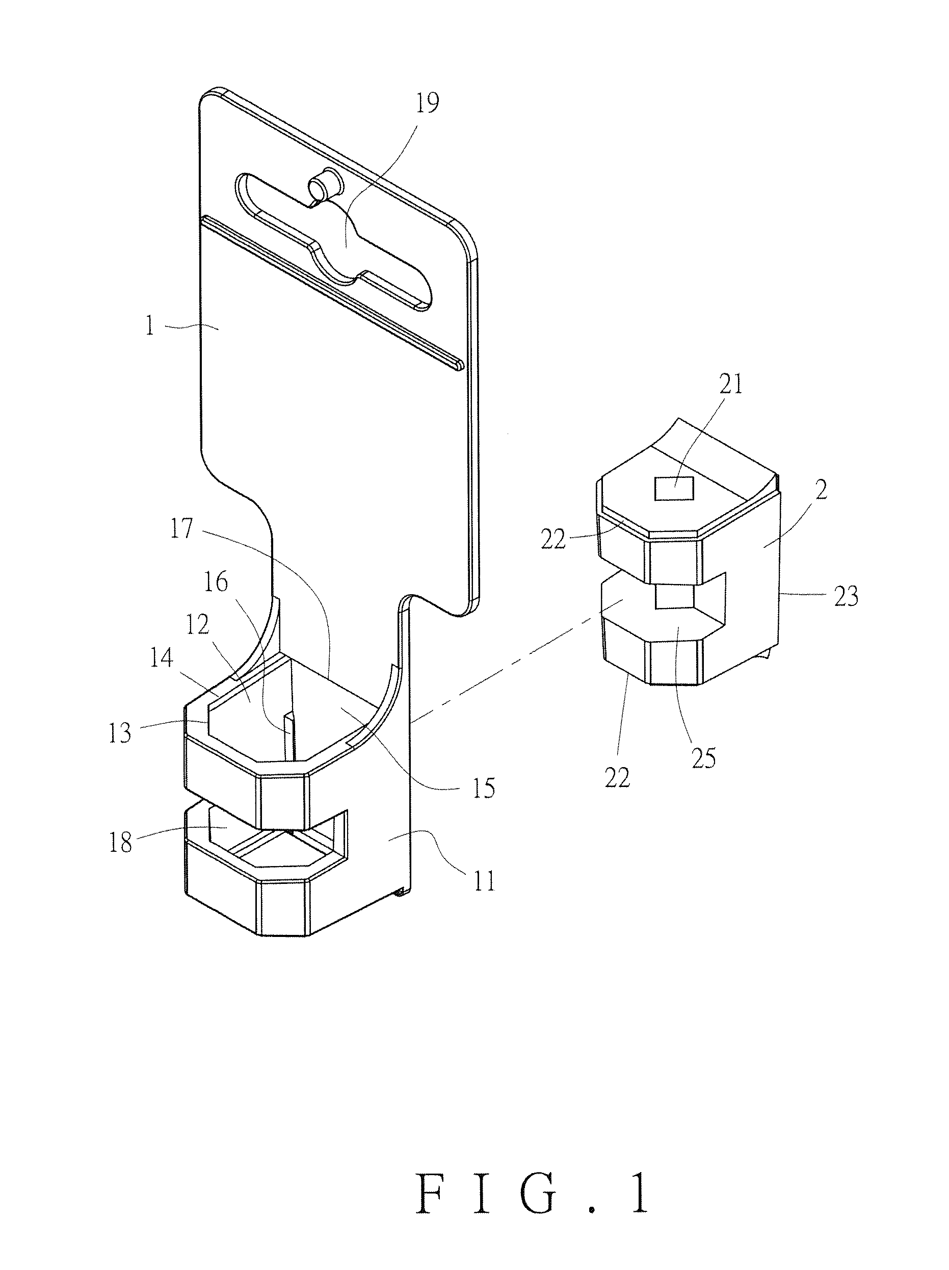
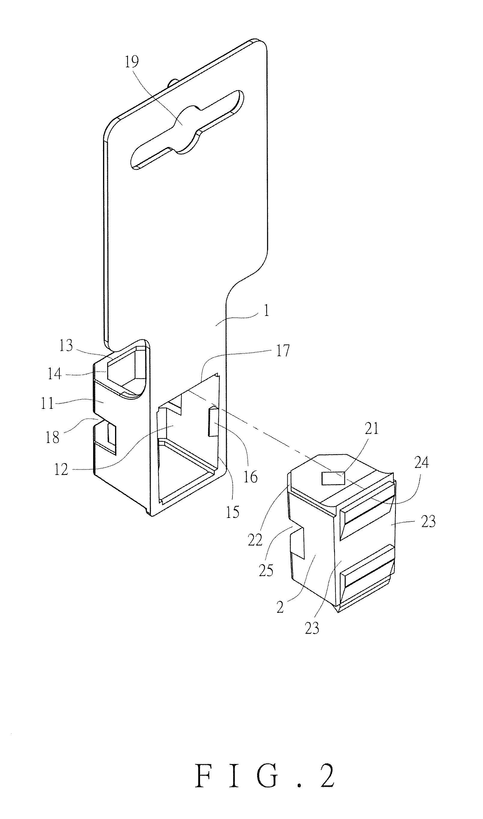
[0029]Referring to FIG. 1 through FIG. 3, an embodiment of the present invention includes a hanger body I and a fixing base 2.

[0030]The hanger body 1 is provided with a fixing portion 11. The fixing portion 11 is provided therein with a receiving space 12 (see FIG. 5). A through hole 13 in communication with the receiving space 12 is provided at each of a top portion and a bottom portion of the fixing portion 11. The periphery of each of the two through holes 13 of the fixing portion 11 is protrudingly provided with a first engaging portion 14, wherein each of the two first engaging portions 14 is a protruding block having an L-shaped cross section. Also, the back of the fixing portion 11 is provided with an access opening 15 in communication with the receiving space 12. The fixing portion 11 is further provided with a first stop block 16 at each of two opposite lateral sides of the access opening 15. An upper edge of the access opening 15 is provided with a transverse first blockin...


PUM


Abstract

A hand tool display hanger includes a hanger body and a fixing base. The hanger body contains a fixing portion. The fixing portion has a receiving space, a through hole, a first engaging portion, an access opening, a first stop block, and a first blocking portion, wherein the through hole and the access opening communicate with the receiving space. The fixing base is fixed in the receiving space and is provided with an insertion hole, a second engaging portion, a second blocking portion, and a second stop block, the latter three of which are respectively engaged with the first engaging portion, the first stop block, and the first blocking portion to prevent the fixing base from falling out of the fixing portion. The display hanger can be rapidly assembled, and a hand tool can be inserted in the insertion hole to achieve a visually pleasing, anti-theft display.

Description

BACKGROUND OF THE INVENTION[0001]1. Technical Field[0002]The present invention relates to hand tool display hangers and, more particularly, to a hand tool display hanger which can be rapidly assembled for a visually pleasing display, which has multiple engaging / blocking features, and which can hinder unauthorized removal of the hand tool fixed therein.[0003]2. Description of Related Art[0004]To facilitate transaction, hand tools for sale are generally fixed on display hangers for display. The structure of such display hangers is disclosed in Taiwan Utility Model Patent No. M436401, issued on Sep. 1, 2012 and titled “Display Base for Precision Tools”, wherein the display base includes a display unit and a connecting mechanism and can be converted between a planar display position and a three-dimensional display position. The display unit includes two spaced-apart lateral display panels on which precision tools can be disposed. The display unit also includes at least one connecting di...

Claims


Application Information

Patent Timeline
Patent Type & Authority Applications(United States)
IPC IPC(8): B25H3/00B65D73/00
CPCB65D73/0064B25H3/006
Inventor HU, CHENG-TE
Owner GONG FONG ENTERPRISE
Why Eureka
Try Eureka