Secondary battery, battery pack, electronic apparatus, electric tool, electric vehicle, and power storage system

a technology of secondary batteries and battery packs, which is applied in the direction of secondary cells, secondary cell servicing/maintenance, and wound/folded electrode electrodes, etc., can solve the problems of difficult to meet the demand for further improvement in the performance of secondary batteries, fracturing of the positive electrode, and the active material layer of the positive electrode becoming prone to fall off from the positive electrode collector, etc., to achieve secure the battery characteristics, suppress the fracturing, and suppress the fra

Active Publication Date: 2015-08-06
MURATA MFG CO LTD
View PDF5 Cites 0 Cited by
  • Summary
  • Abstract
  • Description
  • Claims
  • Application Information

AI Technical Summary

Benefits of technology

[0010]Although a variety of measures and the like have been proposed to suppress the fracturing of the positive electrode when coiling, there is cause, naturally, to not only suppress the fracturing of the positive electrode but to also secure the battery characteristics such as the battery capacity or the cycle characteristics. The reason is that even if fracturing of the positive electrode is able to be suppressed, if the usual performance of the battery is lowered, it is difficult to meet the demand for further improvements in the performance of secondary batteries. In particular, in order to realize higher capacity, being able to suppress fracturing of the positive electrode even when the outer diameter of the coil core rod is reduced and the volume occupied by the positive electrode and the negative electrode within the secondary battery is increased while the thickness of the positive electrode collector is reduced and the thickness of the positive electrode active material layer is relatively increased is ideal.
[0015]According to the secondary battery of the embodiment, the ratio A / (A+B) of the area density A of the inner circumference side positive electrode active material layer and the area density B of the outer circumference side positive electrode active material layer, the inner diameter of the coil opening portion C, the ratio D / E of the thickness D of the positive electrode and the thickness E of the positive electrode collector, and the length F of the single side active material formation region satisfy the relationships shown in Formulae 1 and 2. In such a case, the relationship between the area densities A and B in the relationship with the inner diameter C and the thicknesses D and E is optimized, and the length F in the relationship between the thicknesses D and E is optimized Therefore, even when the inner diameter C is decreased (C=2.5 mm to 4 mm) in order to increase the volume occupied by the positive electrode within the secondary battery and the ratio D / E is increased (D / E=13.333 to 20) in order to increase the volume occupied by the inner circumference side positive electrode active material layer and the outer circumference side positive electrode active material layer within the positive electrode, the positive electrode is not easily fractured when coiling and battery capacity and cycle characteristics are secured. It is therefore possible to obtain excellent battery characteristics while suppressing fracturing of the positive electrode when coiling. Further, the same effects are able to be obtained by the battery pack, the electronic apparatus, the electric tool, the electric vehicle, and the power storage system of the embodiments of the disclosure which use the secondary battery described above.

Problems solved by technology

The reason is that even if fracturing of the positive electrode is able to be suppressed, if the usual performance of the battery is lowered, it is difficult to meet the demand for further improvements in the performance of secondary batteries.
However, in such a case, although fracturing of the positive electrode is suppressed since the flexibility of the positive electrode active material layer increases, since the adhesiveness of the positive electrode active layer to the positive electrode collector is reduced if the thickness of the positive electrode active material layer is increased, the positive electrode active material layer becomes prone to fall off from the positive electrode collector.
On the other hand, if the addition amount of the binder is increased in order to improve the adhesiveness, since the flexibility of the positive electrode active material layer is decreased, fracturing of the positive electrode is caused.

Method used


Image

  • Secondary battery, battery pack, electronic apparatus, electric tool, electric vehicle, and power storage system
  • Secondary battery, battery pack, electronic apparatus, electric tool, electric vehicle, and power storage system
  • Secondary battery, battery pack, electronic apparatus, electric tool, electric vehicle, and power storage system

Examples


examples

[0099]Examples of the embodiments of the disclosure will be described in detail.

Experiments 1 to 35

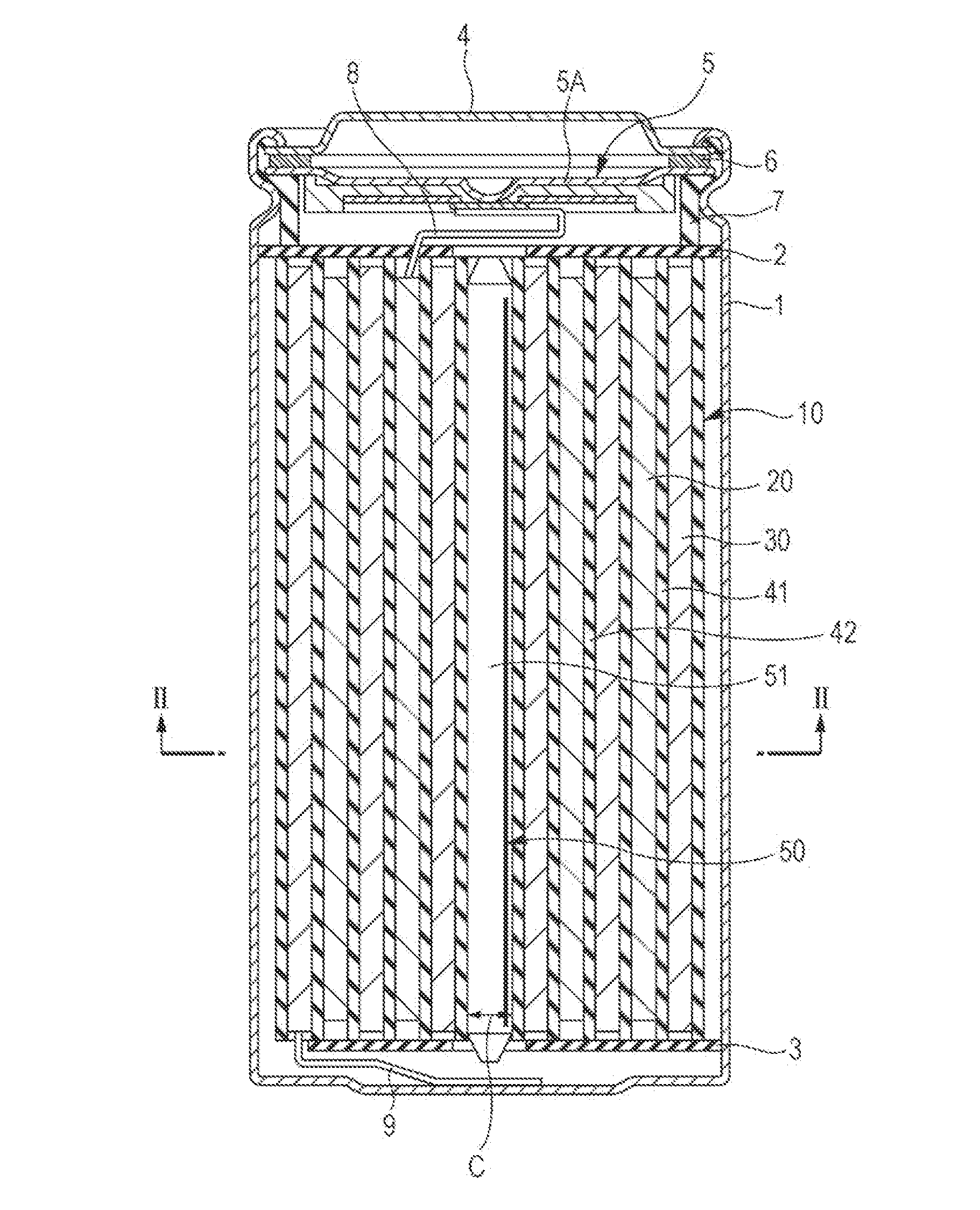
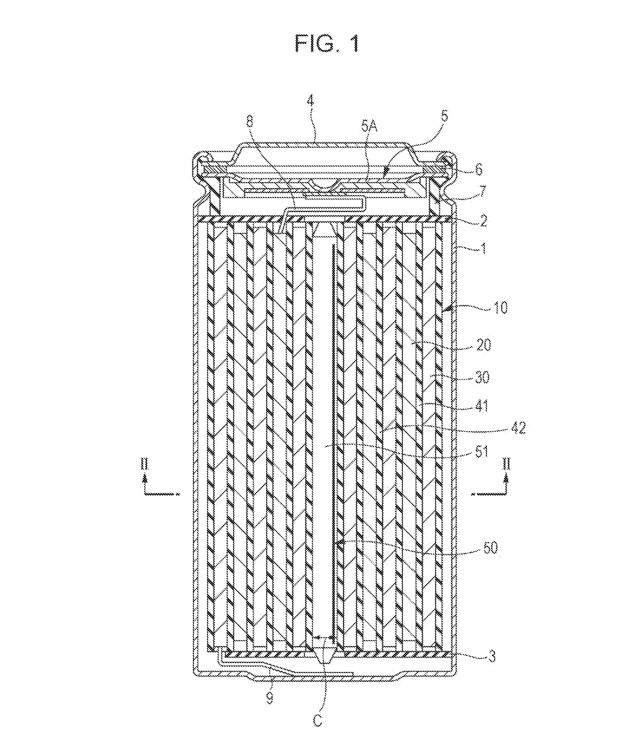
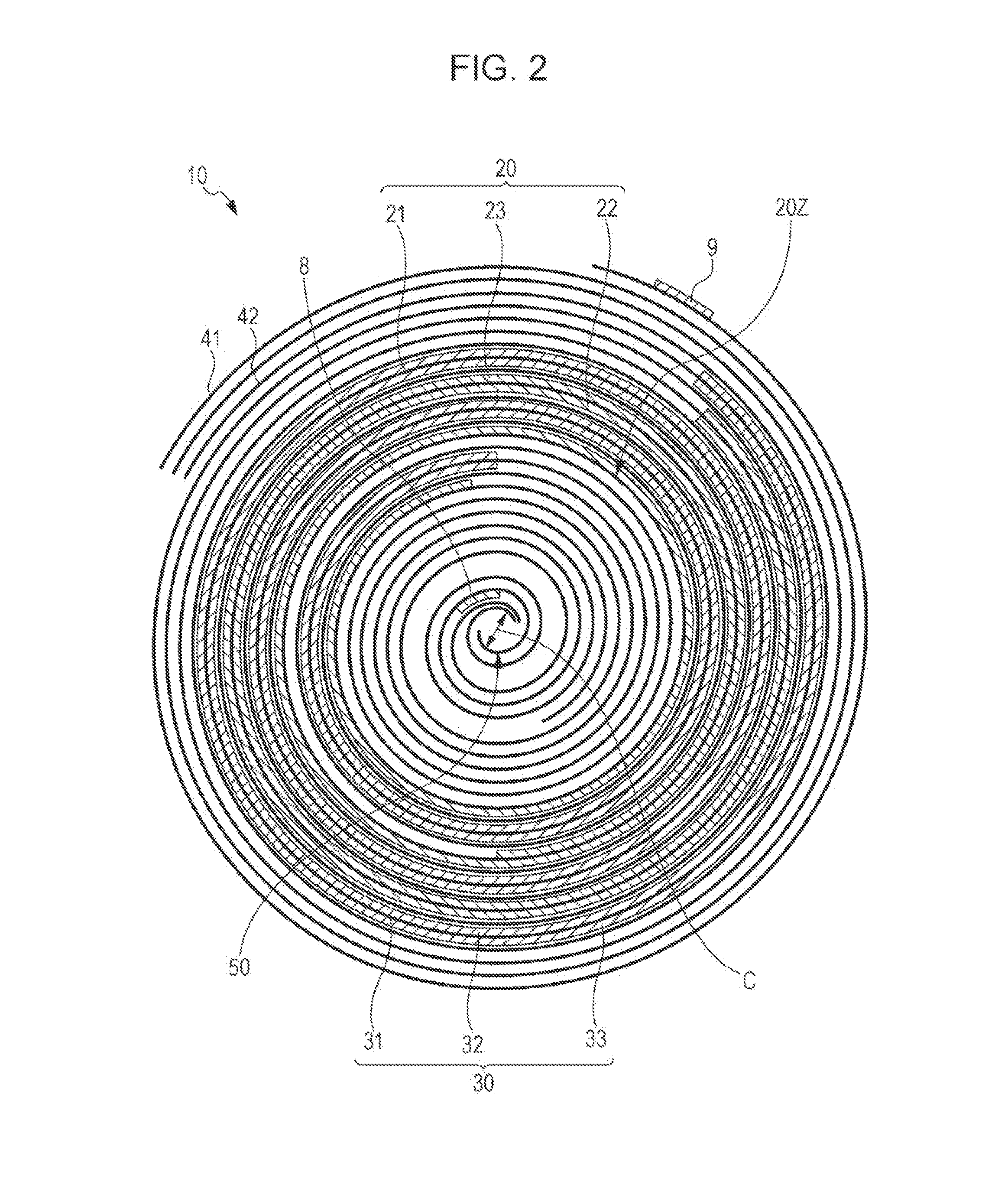
[0100]The cylindrical secondary battery (lithium ion secondary batter) illustrated in FIGS. 1 to 4B was created by the following steps.

[0101]First, the positive electrode 20 (thickness D: Tables 1 to 3) were created. In such a case, a lithium cobalt composite oxide (LiCoO2) was obtained by mixing lithium carbonate (Li2CO3) and cobalt carbonate (CoCO3) in a molar ratio of Li2CO3:CoCO3=0.5:1 and calcining in air (900° C.×5 hours). Next, after creating a positive electrode compound by mixing 91 parts by mass of the positive electrode active material (LiCoO2), 3 parts by mass of the positive electrode binder (polyvinylidene fluoride), and 6 parts by mass of the positive electrode conductive agent (graphite), the positive electrode compound was dispersed in the solvent (N-methyl-2-pyrrolidone) to form the paste-like positive electrode compound slurry. Finally, the inner circumference side p...


PUM

PropertyMeasurementUnit
diffraction angle 2θaaaaaaaaaa

Abstract

A secondary battery including: spirally wound electrode body in which positive electrode and negative electrode are laminated via separator and spirally wound, wherein the positive electrode includes an inner circumference side positive electrode active material layer and an outer circumference side positive electrode active material layer while including a single side active material layer formation region, the ratio A / (A+B) of an area density A (mg / cm2) of the inner circumference side positive electrode active material layer and an area density B (mg / cm2) of the outer circumference side positive electrode active material layer, an inner diameter C (mm) of the coil opening portion, and the ratio D / E of a thickness D (μm) of the positive electrode and a thickness E (μm) of the positive electrode collector satisfy the relationship expressed in Formula 1, and a length F (mm) of the single side active material layer formation region satisfies the relationship expressed in Formula 2.

Description

CROSS REFERENCES TO RELATED APPLICATIONS[0001]The present application is a continuation of U.S. patent application Ser. No. 13 / 312,521, filed on Dec. 6, 2011, which claims priority to Japanese Priority Patent Application JP 2010-276716 filed in the Japan Patent Office on Dec. 13, 2010, the entire content of which is hereby incorporated by reference.BACKGROUND[0002]The present application relates to a secondary battery that includes a spirally wound electrode body in which a positive electrode and a negative electrode are laminated and spirally wound via a separator, and a battery pack, an electronic apparatus, an electric tool, an electric vehicle, and a power storage system that use such a secondary battery.[0003]In recent years, electronic apparatuses typified by mobile terminal apparatuses and the like have been popularized, and there is demand for such apparatuses to be further miniaturized, lightened, and to have a longer service life. Accordingly, the development of a battery,...

Claims


Application Information

Patent Timeline
Patent Type & Authority Applications(United States)
IPC IPC(8): H01M10/04H01M4/583H01M4/38
CPCH01M10/0431H01M10/42H01M2010/4292H01M4/583H01M4/38H01M4/386H01M4/387Y02E60/122Y02E60/10Y02P70/50
Inventor TOKUNAGA, TAKASHIFUKAHORI, HIRONOBU
Owner MURATA MFG CO LTD
Why Eureka
Try Eureka