Lens barrel and optical apparatus having the same

a technology of optical apparatus and lens barrel, applied in the field of lens barrel, to achieve the effect of stabilizing the optical elemen

Active Publication Date: 2015-08-13
CANON KK
View PDF7 Cites 9 Cited by
  • Summary
  • Abstract
  • Description
  • Claims
  • Application Information

AI Technical Summary

Benefits of technology

[0006]The present invention provides a lens barrel that can provide an optical axis adjustment that accords an optical axis of an optical element with a center axis of a barrel body and can stably hold the optical element having the adjusted optical axis even in a high temperature environment.

Problems solved by technology

However, the configuration disclosed in JP 07-209567 is not suitable for the lens barrel that requires a highly precise maintenance of the optical axis below the engagement error between the barrel and the contact member, and this problem becomes remarkable in a high temperature environment due to the thermal expansion difference between the materials.

Method used


Image

  • Lens barrel and optical apparatus having the same
  • Lens barrel and optical apparatus having the same
  • Lens barrel and optical apparatus having the same

Examples


Embodiment Construction

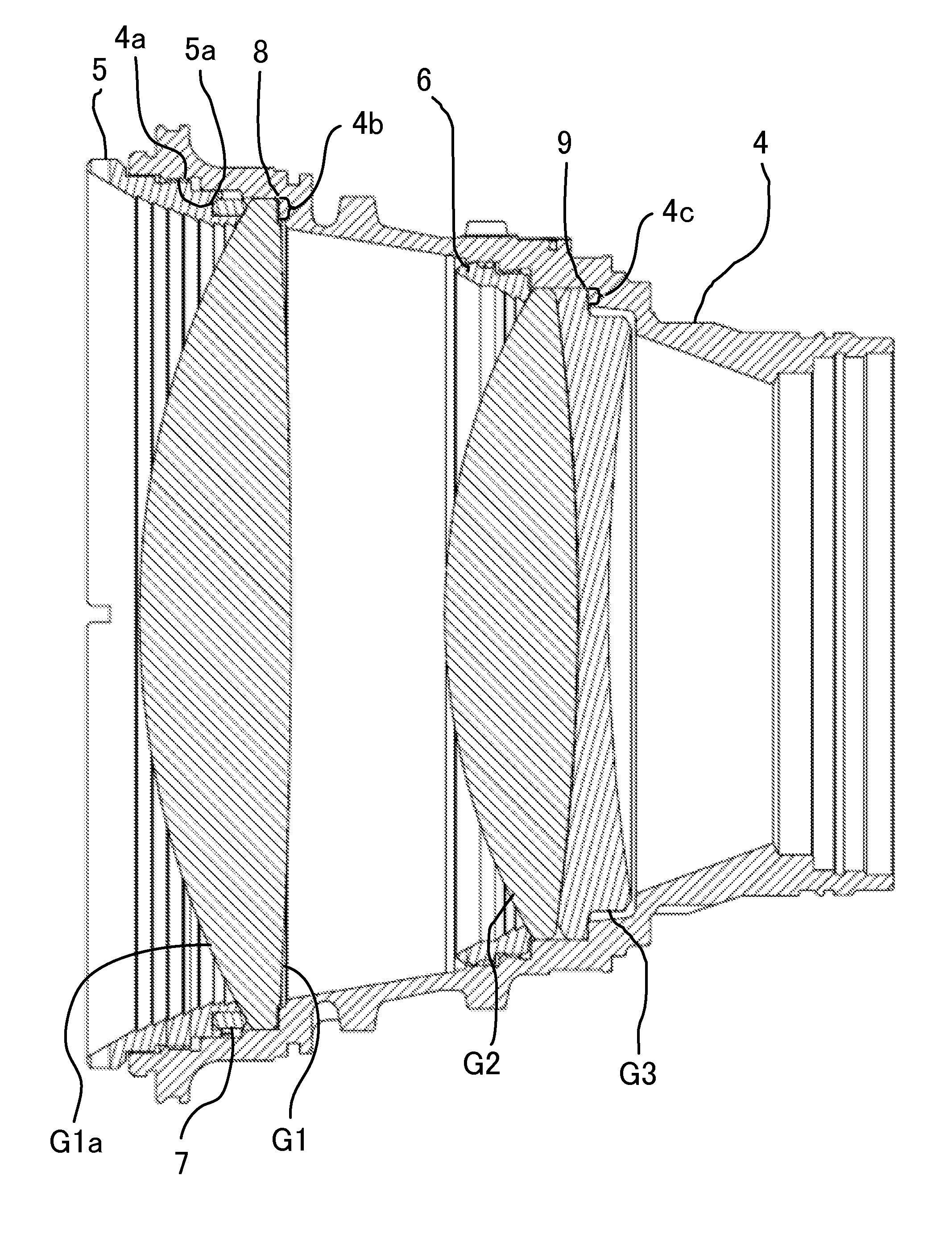
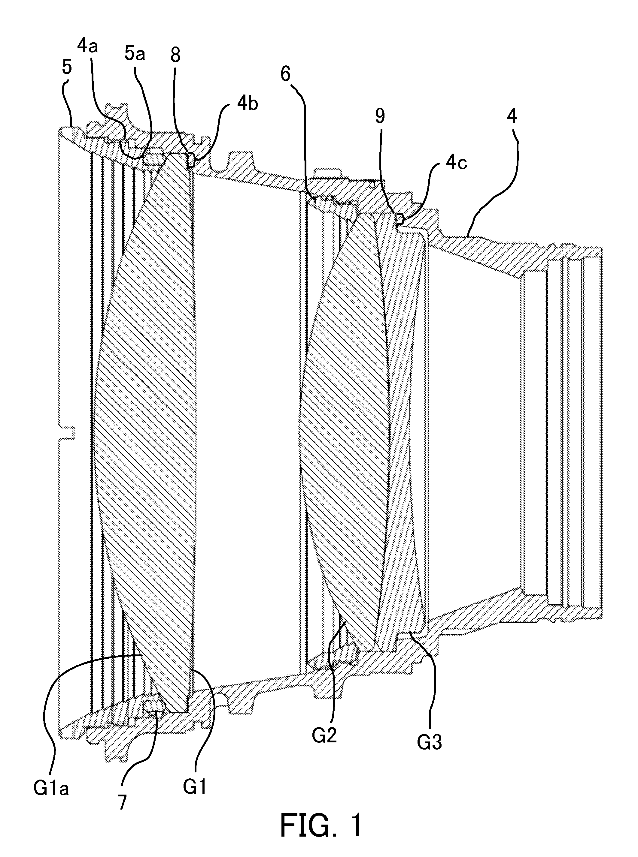
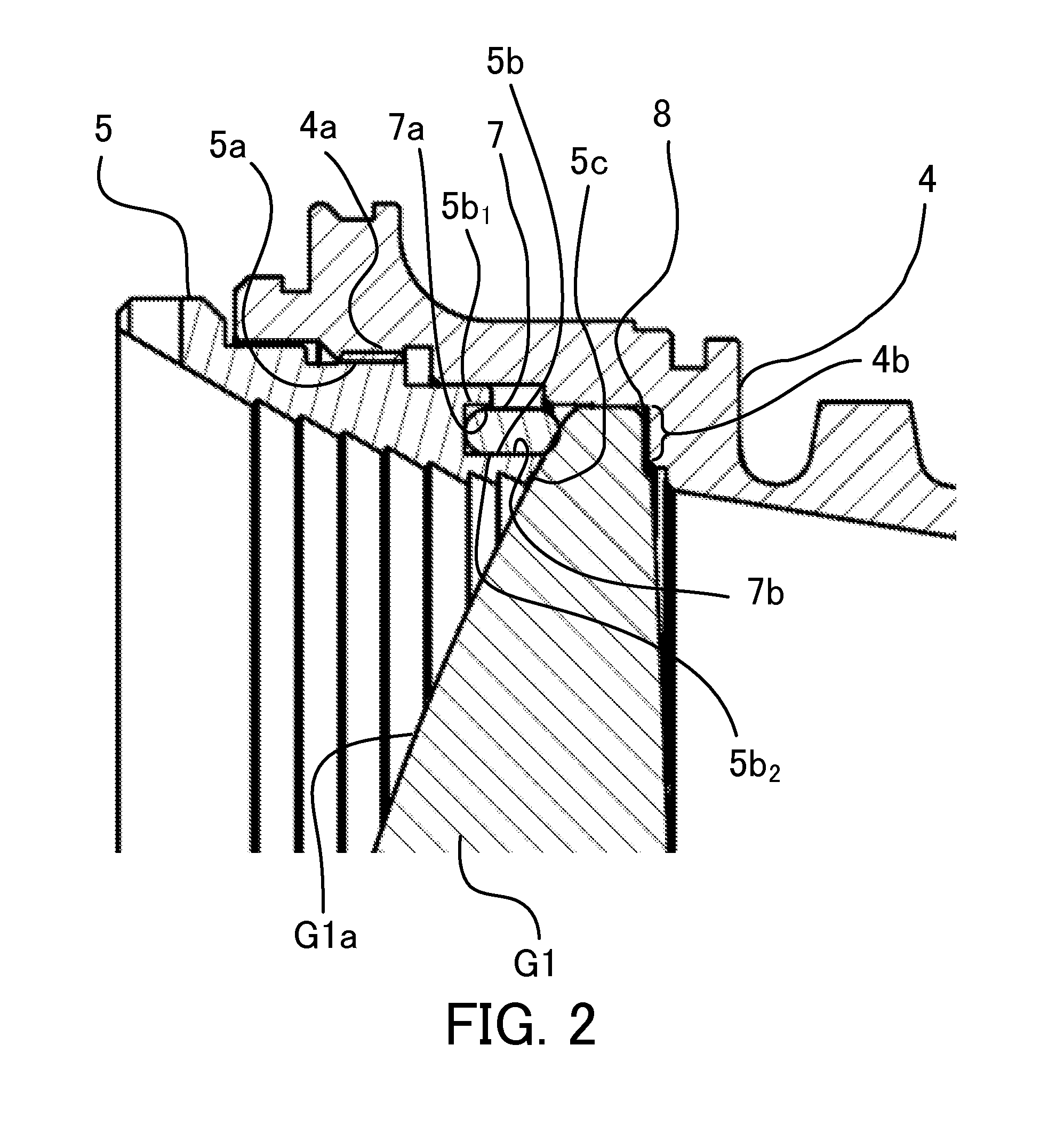
[0013]FIG. 1 is a sectional view of a lens barrel according to this embodiment. FIG. 2 is a partially enlarged sectional view of FIG. 1. FIG. 3 is an exploded perspective view of the lens barrel illustrated in FIG. 1.

[0014]The lens barrel holds an optical system that includes optical elements G1, G2, and G3, and can be attached to and detached from a camera body (or image-pickup apparatus body) (not illustrated). In this case, the optical system serves as an image-pickup optical system configured to form an optical image of an object. The lens barrel may be integrated with the camera body. The image-pickup apparatus may be a digital still camera or a digital video camera. Moreover, the present invention is applicable to an optical apparatus, such as binoculars, a microscope, a measuring apparatus, and a laser.

[0015]In FIGS. 1 to 3, the optical elements G1, G2, and G3 are made of a transparent material, such as glass. In this embodiment, the optical element G1 is a convex lens, the o...


PUM


Abstract

A lens barrel includes an optical element, a barrel body configured to hold the optical element, the barrel body including a female thread, a presser including a male thread fastened to the female part and contacting the optical element, and an elastic member held by the presser, wherein in a fastening state in which the male thread is fastened to the female thread, both the presser and the elastic member contact the optical element, and the elastic member applies a force in a direction of fixing the optical element onto the barrel body

Description

BACKGROUND OF THE INVENTION[0001]1. Field of the Invention[0002]The present invention relates to a lens barrel.[0003]2. Description of the Related Art[0004]In mounting an optical element in a lens barrel, an optical axis adjustment is often necessary in which an optical axis of the optical element is accorded with a center axis of a barrel body so as to maintain the optical performance. Japanese Patent Laid-Open No. (“JP”) 07-209567 provides an optical element with an inclined surface that contacts a barrel body, and arranges a contact member on the barrel body, which has an inclined surface and slides relative to the optical element via an elastic member. JP 2005-148254 proposes a press ring that holds an elastic member and supports glass. JP 05-127058 proposes a presser holds an optical element via an elastic member.[0005]However, the configuration disclosed in JP 07-209567 is not suitable for the lens barrel that requires a highly precise maintenance of the optical axis below the...

Claims


Application Information

Patent Timeline
Patent Type & Authority Applications(United States)
IPC IPC(8): G02B7/02G02B7/00
CPCG02B7/028G02B7/003G02B7/022G02B7/021G02B7/026
Inventor SUGITA, JUN
Owner CANON KK
Why Eureka
Try Eureka