Supercharge Your Innovation With Domain-Expert AI Agents!

Electricity storage device

a technology of storage device and electric power, which is applied in the direction of batteries, cell components, vent arrangements, etc., can solve the problems that the cooling path of the battery and the discharge path of the gas produced inside the battery (the smoke discharge path) cannot be separated from each other

Active Publication Date: 2015-08-13
TOYOTA JIDOSHA KK
View PDF4 Cites 7 Cited by
  • Summary
  • Abstract
  • Description
  • Claims
  • Application Information

AI Technical Summary

Benefits of technology

The invention is an electricity storage device that separates the battery cooling path from the smoke discharge path. The technical effect is to improve the safety and reliability of the device.

Problems solved by technology

However, in the construction described in JP-A-2012-109126, the air that cools the electricity storage elements flows from an intake opening that is provided on the opposite side to the side provided with valves toward a discharge opening that is provided on the valve-provided side, and this flowing direction gives rise to a problem that a cooling path for the battery and a discharge path for gas produced inside the battery (a smoke discharge path) cannot be separated from each other.

Method used


Image

  • Electricity storage device
  • Electricity storage device
  • Electricity storage device

Examples


Embodiment Construction

[0028]Best modes for carrying out the invention will be described hereinafter with reference to the drawings.

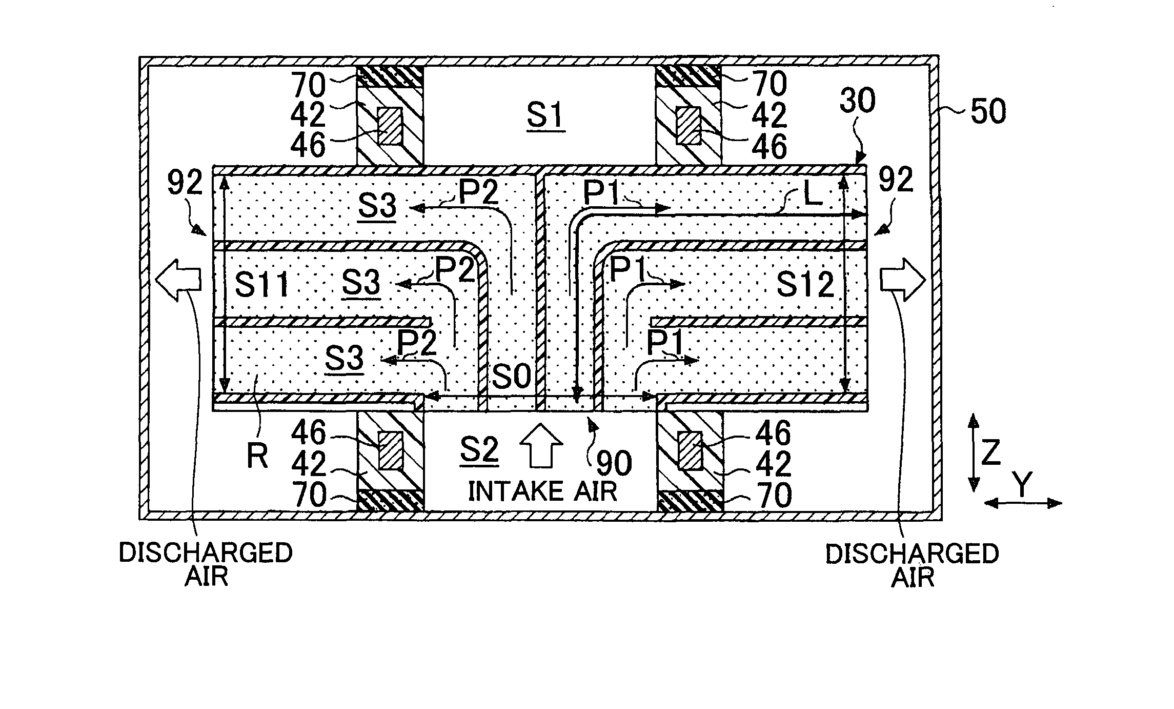
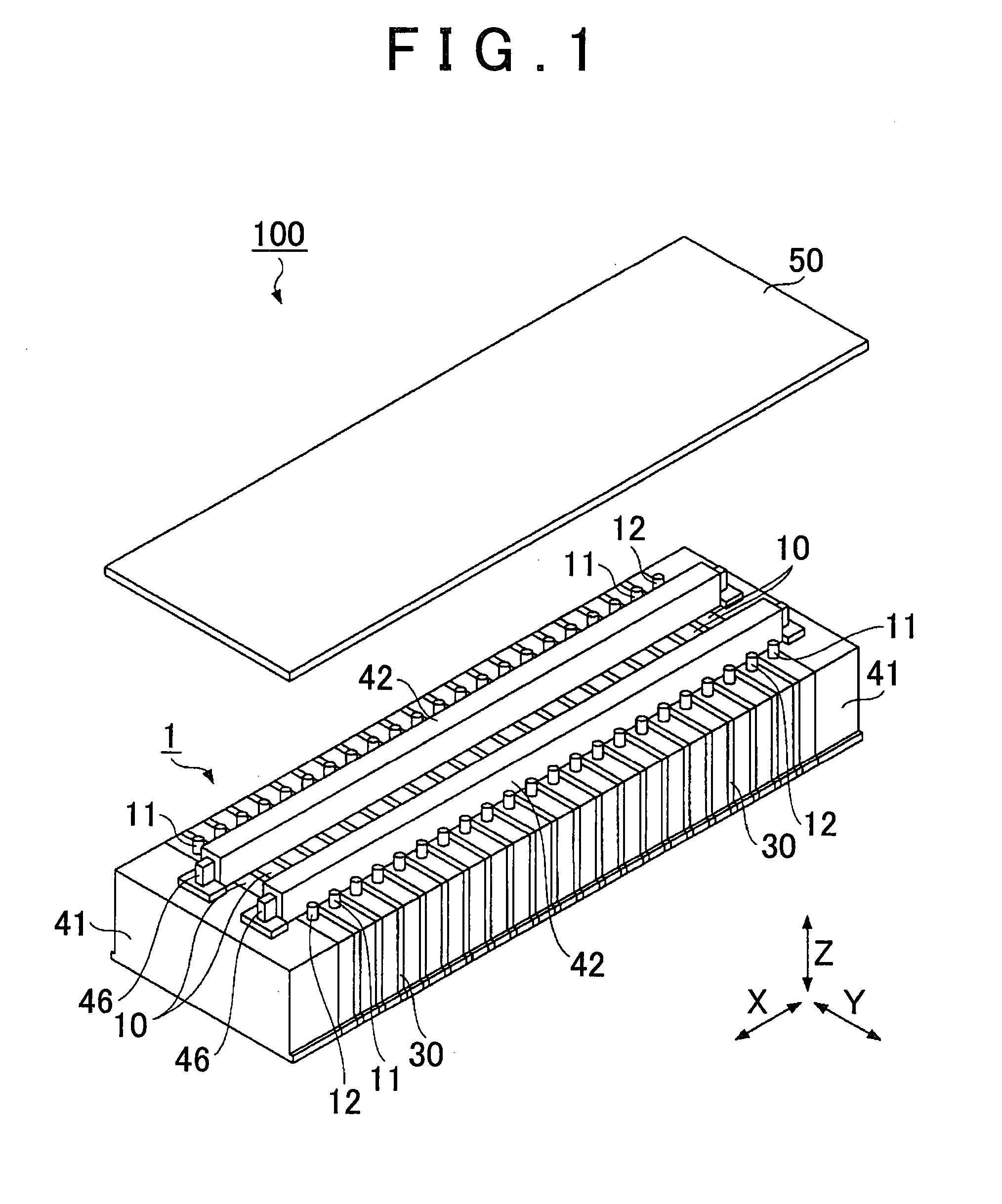
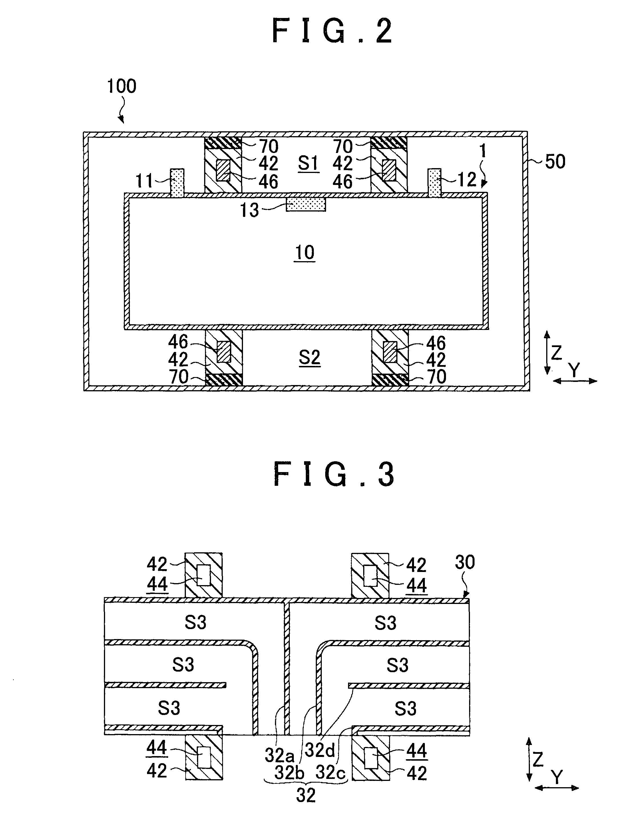
[0029]FIG. 1 is an external view schematically showing a battery pack 100 according to an embodiment of the invention. In FIG. 1, a pack case 50, only an upper portion of which is shown, is apart from a battery stack 1 for the sake of convenience in illustration. FIG. 2 is a diagram schematically showing a sectional view of the battery pack 100 taken on a Y-Z plane. In FIG. 1 and FIG. 2, X directions, Y directions and Z directions are orthogonal to one another. Incidentally, although up-down directions, left-right directions, etc. change according to the mounted state of the electricity storage device or the direction of view, it is assumed in the following description that the Z directions correspond to vertical directions (up-down directions) and an upper side in the drawings is an “upper side” with reference to the illustration in each drawing, for the sake of convenience....


PUM

PropertyMeasurementUnit
areaaaaaaaaaaa
arresting forceaaaaaaaaaa
T shapeaaaaaaaaaa

Abstract

An electricity storage device includes: a plurality of batteries juxtaposed in a first direction, each battery having on a first side a gas discharge valve that discharges a gas produced inside the battery; and a cooling path formed between the plurality of batteries that face each other in the first direction, constructed to convey a coolant that cools the batteries, and an intake opening for taking in the coolant on a second side that is an opposite side to the first side in a second direction orthogonal to the first direction and a discharge opening for discharging the coolant taken in on at least one of sides in a third direction orthogonal to the second direction and to the first direction.

Description

BACKGROUND OF THE INVENTION[0001]1. Field of the Invention[0002]The invention relates to an electricity storage device.[0003]2. Description of Related Art[0004]There exists an electricity storage device which has: a plurality of electricity storage elements that are juxtaposed in a predetermined direction and that is each equipped with a valve that discharges gas produced inside; a pair of end plates that clamp the electricity storage elements in the predetermined direction; a plurality of connecting members that extend in the predetermined direction and that are fixed to the two end plates; and a case for housing the electricity storage elements, and in which the connecting members are disposed along external surfaces of the electricity storage elements on which the valves are provided, and contact an internal wall surface of the case, and form, together with the case, a space in which gas discharged from the valves moves (see, e.g., Japanese Patent Application Publication No. 2012...

Claims


Application Information

Patent Timeline
Patent Type & Authority Applications(United States)
IPC IPC(8): H01M2/12H01M2/10H01M50/209H01M50/276H01M50/289
CPCH01M2/12H01M10/613H01M2220/20H01M10/625H01M2/1077H01M50/30H01M50/333H01M50/289H01M50/209H01M50/276H01M10/6563H01M10/647H01M10/6556H01M10/6557Y02E60/10H01M50/20
Inventor NAGAMINE, KOICHIKITAMURA, MASAHIKO
Owner TOYOTA JIDOSHA KK
Features
  • R&D
  • Intellectual Property
  • Life Sciences
  • Materials
  • Tech Scout
  • Unparalleled Data Quality
  • Higher Quality Content
  • 60% Fewer Hallucinations
Learn More