Hinged clamp for spacer-damper

a technology of spacers and clamps, which is applied in the direction of snap fasteners, buckles, maintaining the distance between parallel conductors, etc., can solve the problems of labor-intensive process, large number of spacers typically needed, and damage to individual conductors in bundled electrical transmission lines

Active Publication Date: 2015-08-13
HUBBELL INC
View PDF7 Cites 12 Cited by
  • Summary
  • Abstract
  • Description
  • Claims
  • Application Information

AI Technical Summary

Benefits of technology

[0009]Other embodiments, including apparatus, systems, methods, and the like which constitute part of the invention, will become more apparent upon reading the following detailed description of the exemplary embodiments and viewing the drawings. It is to be understood that both the foregoing general description and the following detailed description are exemplary and explanatory only and therefore not restrictive.

Problems solved by technology

Damage to individual conductors in bundled electrical transmission lines may be caused by the vibration and oscillation or galloping of the conductors.
The motion of the conductors in a bundle may also be caused by electrical power surges, which cause the conductors in a bundle to be attracted toward the center thereof.
Because the transmission distance is often long, a large number of spacer-dampers are typically needed.
The spacer-dampers must also be manually attached to the conductors, resulting in a labor intensive process.

Method used


Image

  • Hinged clamp for spacer-damper
  • Hinged clamp for spacer-damper
  • Hinged clamp for spacer-damper

Examples


Embodiment Construction

[0023]Reference will now be made in detail to the exemplary embodiment of the invention as illustrated in the accompanying drawings, in which like reference characters designate like or corresponding parts throughout the drawings.

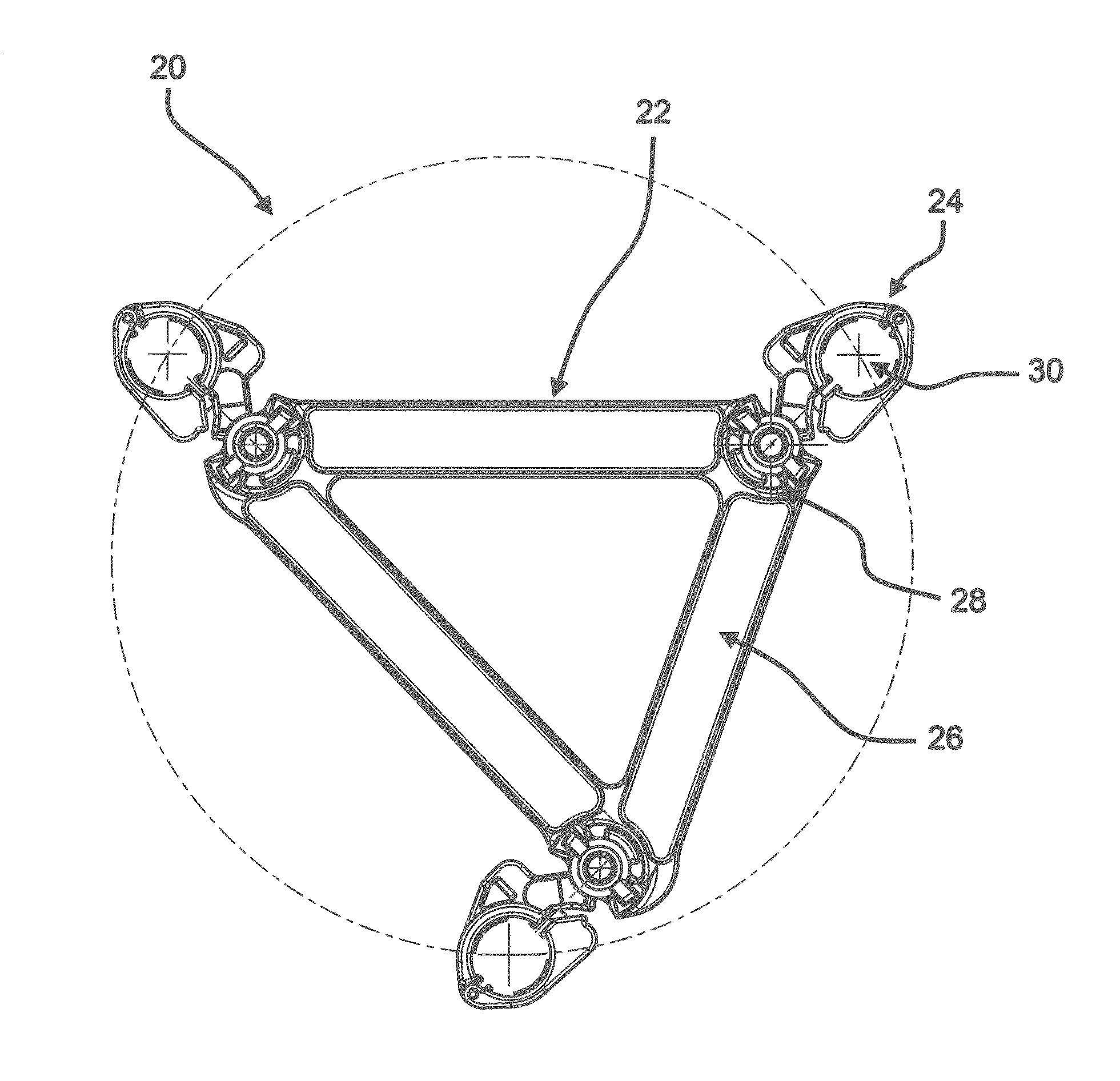
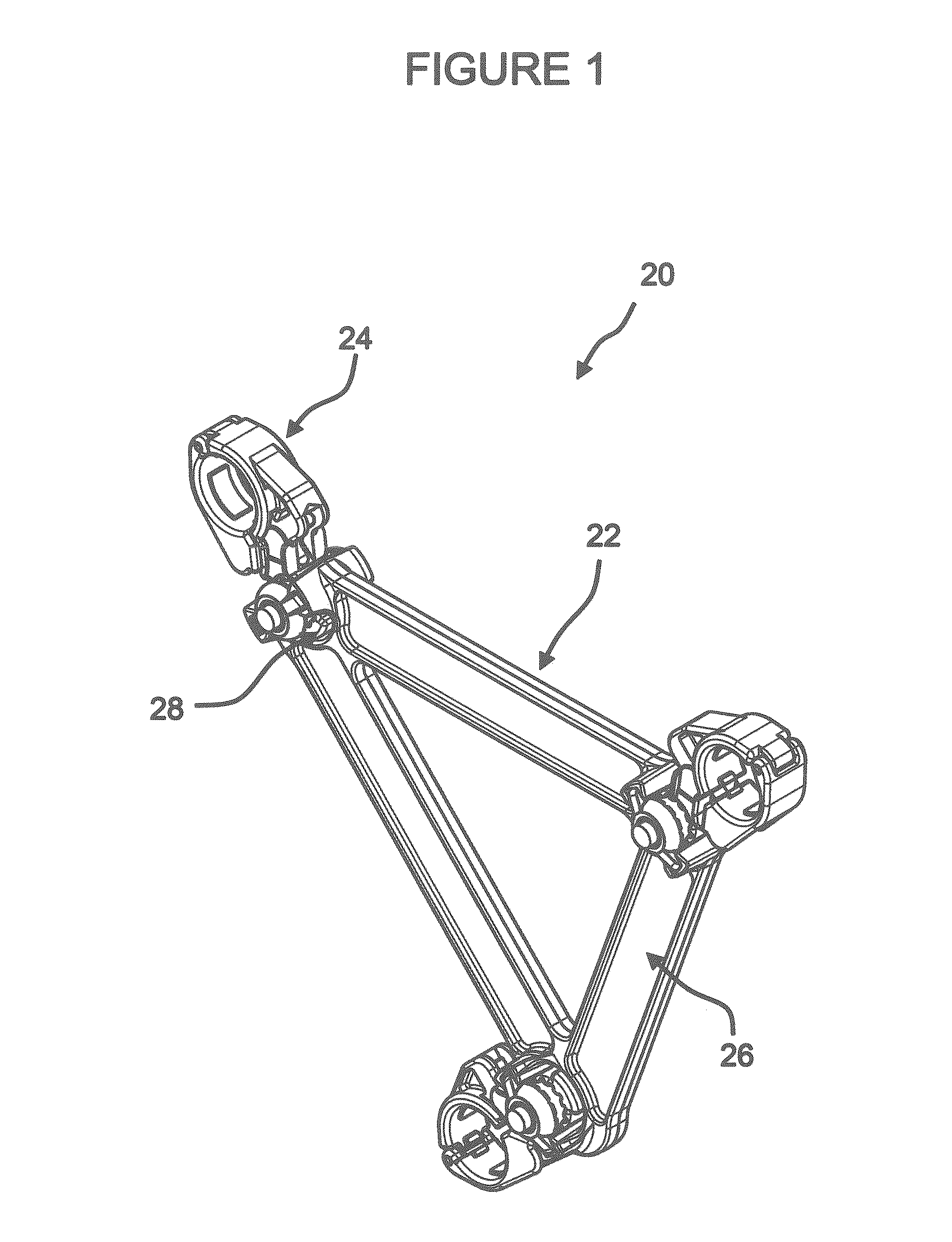
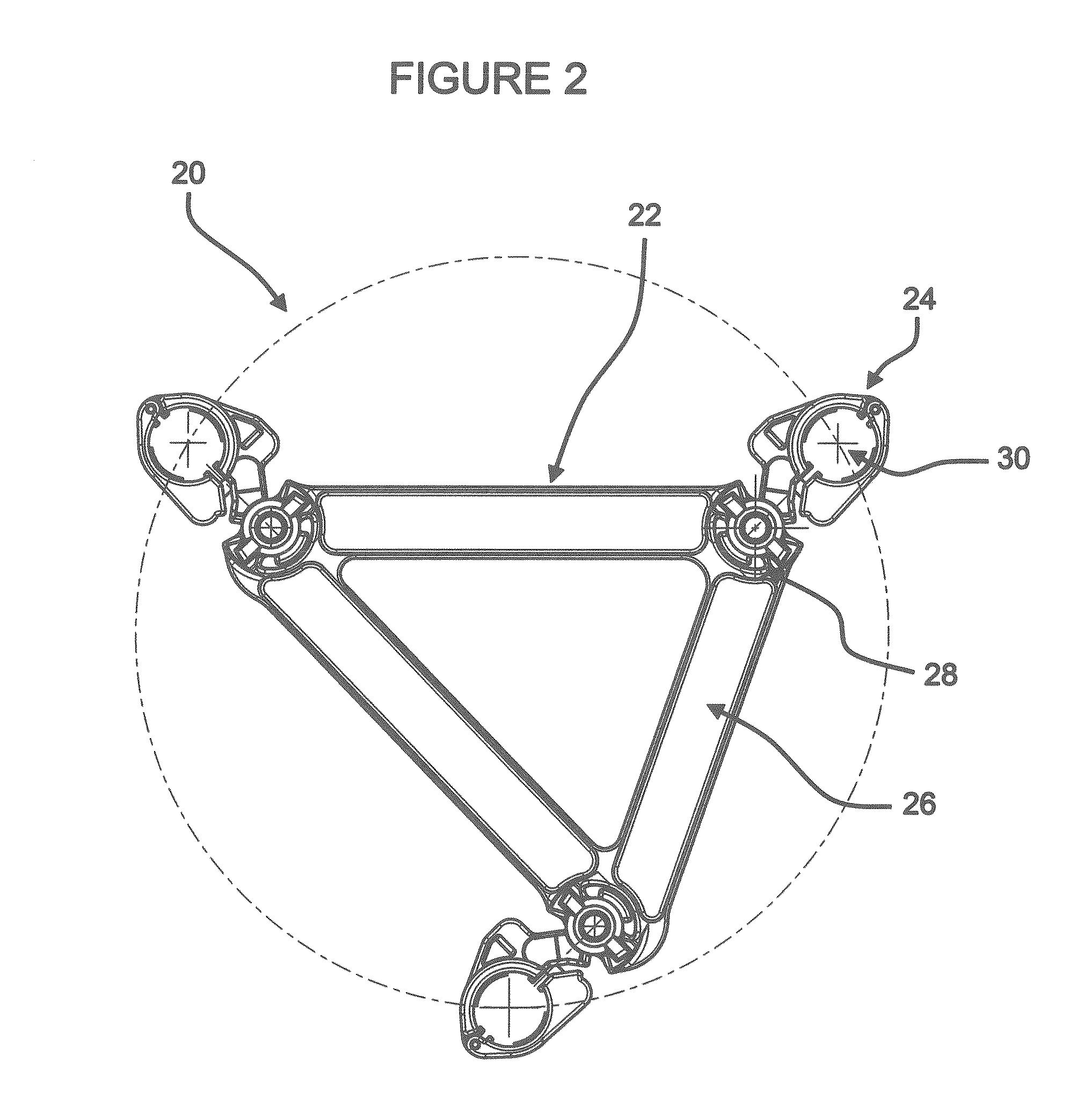
[0024]A spacer-damper 20 includes a frame 22 and a set of clamps 24. The frame 22 includes a plurality of rigid arms 26. The arms 26 may be formed as a unitary structure or may be separately formed and attached to one another. The arms 26 may be metallic, for example an aluminum alloy, or made from any suitable composite material. A corner 28 is formed at the connection of each arm 26 and a clamp 24 is positioned at each corner 28. The clamps 24 are pivotally connected with respect to the frame 22 and extend radially outwardly therefrom. Each clamp 24 includes an opening 30 for receiving a conductor C.

[0025]As best shown in FIG. 2, the center of each opening 30 may lay along a common circle. The clamps 24 may be connected to the frame 22 in a variety of man...


PUM


Abstract

A clamp for a spacer-damper includes a first jaw and a second jaw connected to the first jaw. The first jaw has a first clamping surface and a first aperture. The first aperture retains the fastener in an initial position and in a second position spaced latterly from said initial position. The second jaw has a second clamping surface and an open-ended second aperture. The second aperture receives the fastener in the second position. The first jaw may also include a keeper surface for receiving the fastener in an initial position, a keeper pocket for receiving the fastener in a second position and a keeper protrusion is positioned between the keeper surface and the keeper pocket.

Description

FIELD OF THE INVENTION[0001]The present invention relates to clamps for conductors including spacer-dampers for power transmission lines.BACKGROUND OF THE INVENTION[0002]Utility lines are used to transmit power from a generating facility to a distribution point. Typically, high voltage conductor lines are bundled over long distances to efficiently and economically transfer power and must be spaced from one another to avoid damage.[0003]Damage to individual conductors in bundled electrical transmission lines may be caused by the vibration and oscillation or galloping of the conductors. Such undesired motions may be induced by the wind, and may have longitudinal, transverse and vertical components. Suppression of these vibrations and oscillations requires a resilient connection between the conductors with all the conductors in a bundle being spaced from one another while allowing a limited amount of flexing to occur.[0004]The motion of the conductors in a bundle may also be caused by ...

Claims


Application Information

Patent Timeline
Patent Type & Authority Applications(United States)
IPC IPC(8): H02G7/12F16B2/10
CPCF16B2/10H02G7/125Y10T24/3907H02G1/02
Inventor DOBRINSKI, DANIEL DAVIDCHAN, PETER
Owner HUBBELL INC
Why Eureka
Try Eureka