
Press-forming mold designing method and press-forming mold

a press-forming mold and design method technology, applied in forging/hammering/pressing machines, shaping tools, instruments, etc., can solve the problems of lower press formability of workpieces with higher strength, and achieve stable press forming, improve press forming failure rate, and prevent bendability-dominated fractures

Inactive Publication Date: 2015-08-20
JFE STEEL CORP
View PDF2 Cites 10 Cited by
  • Summary
  • Abstract
  • Description
  • Claims
  • Application Information

AI Technical Summary

Benefits of technology

The present invention prevents bending fatigue (also known as bendability) while shaping metal sheets through pressing. This results in better quality products and reduces failures during production. Additionally, this technology helps create more precise tools for pressing different parts, saving money on research and development.

Problems solved by technology

The technical problem being addressed in this patent text relates to how to improve the ability of metal sheets, especially those made from high-strength steels commonly used in press forming processes, to be shaped without causing damage during the process.

Method used


Image

  • Press-forming mold designing method and press-forming mold
  • Press-forming mold designing method and press-forming mold
  • Press-forming mold designing method and press-forming mold

Examples


examples

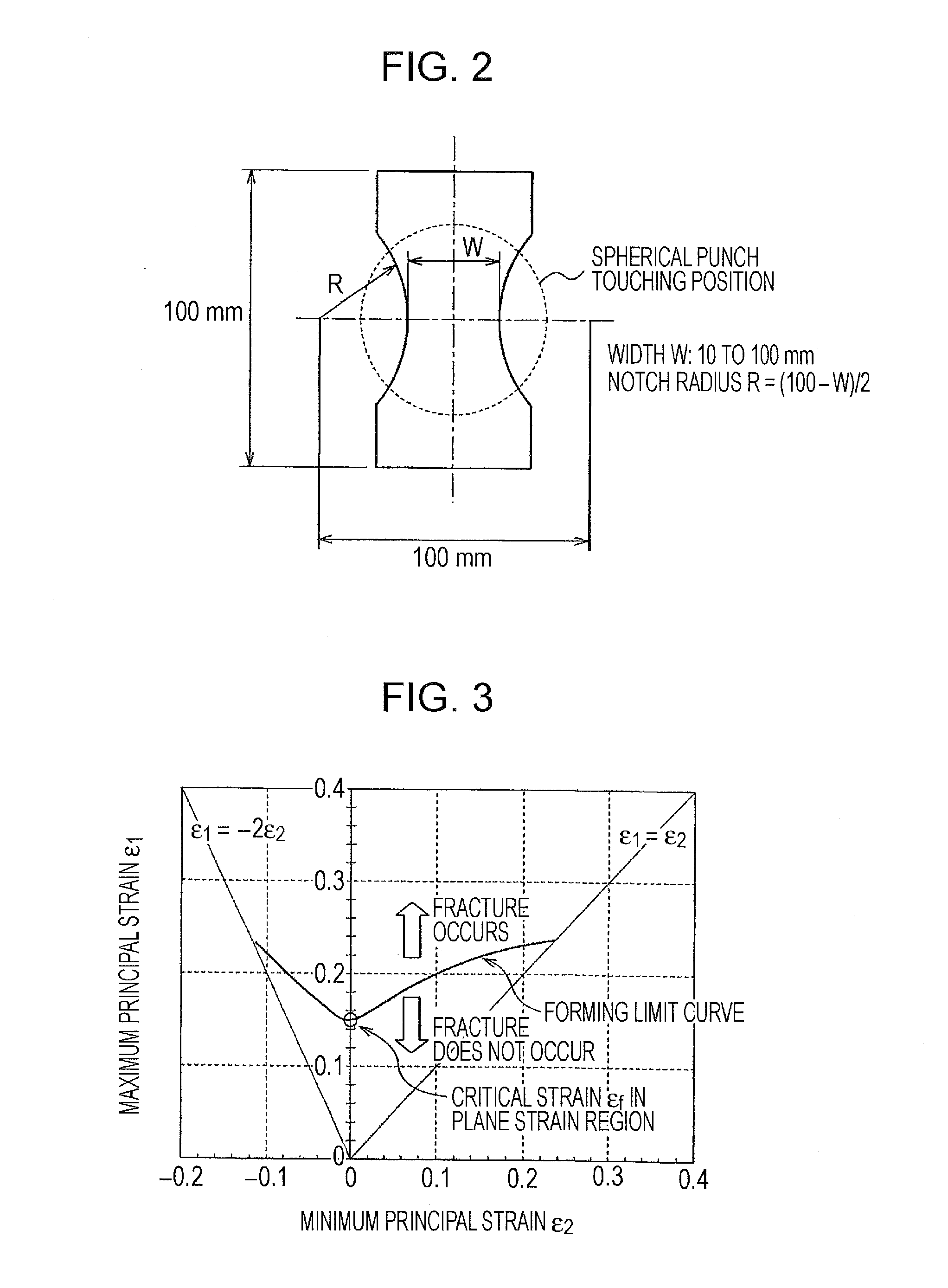
[0044]First, two specimens A and B shown in Table 1 which had substantially equal ductility (total elongation) and different levels of bendability were processed into several kinds of test pieces having a shape illustrated in FIG. 2 and a smallest width of 10 to 100 mm. The surface of the test pieces was subjected to electrolytic etching to form a dot pattern with dot intervals of 1.0 mm. Next, the test pieces were bulge formed with a spherical punch having a minimum curvature radius of the tip of 25 mm. The bulging with the spherical punch was continued until a fracture penetrated the steel sheet. With respect to the bulge formed test pieces, changes in dot intervals that had occurred in the vicinity of the punch tip were measured. The maximum principal strains and the minimum principal strains were thus determined, and a forming limit diagram was prepared.

TABLE 1SheetYield TensileTotalCriticalthickness stressstrength elongation bendingSpec-t YS TSElradius R*Bendabilityimen(mm)(MPa...


PUM

PropertyMeasurementUnit
Radiusaaaaaaaaaa
Strain pointaaaaaaaaaa

Abstract

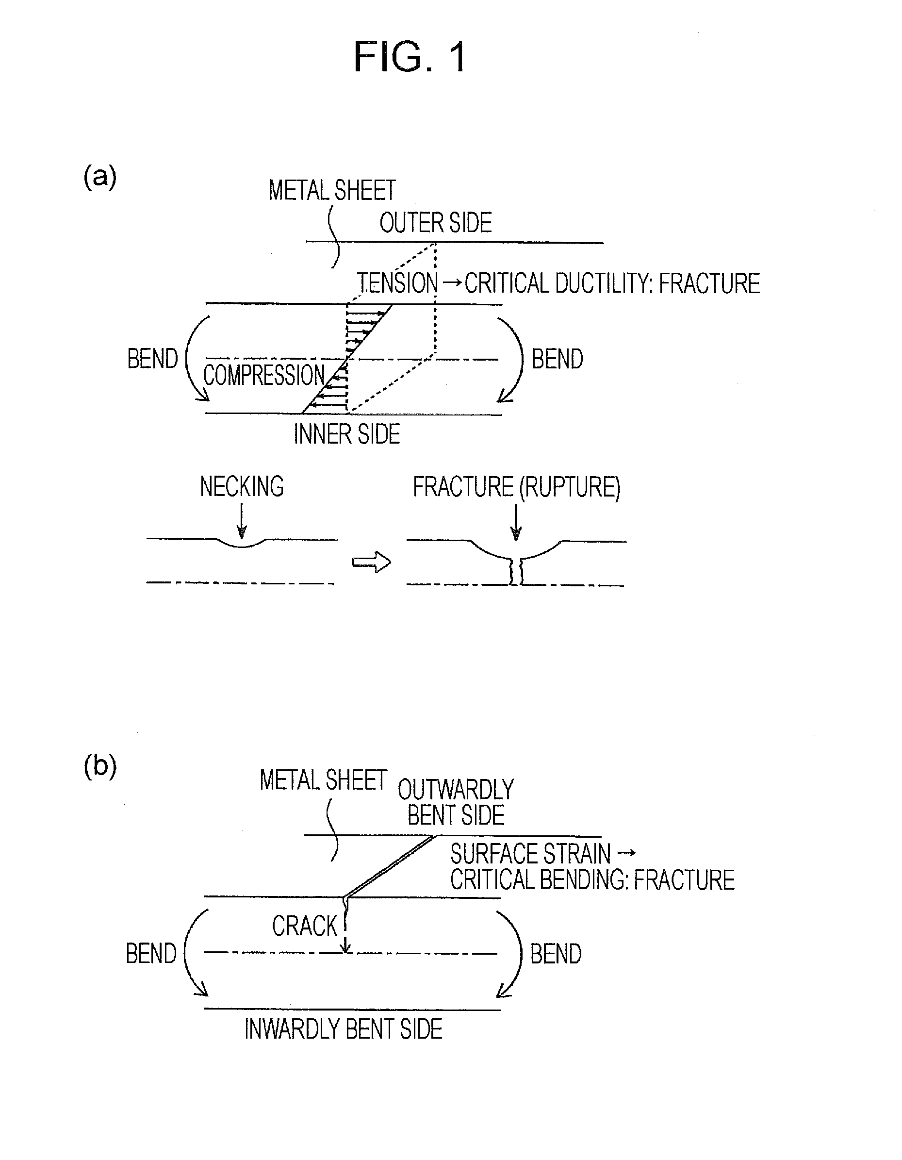
A prediction equation “R0/t(2R/t+(2R/t+1)εf)/2(1−(1+2R/t)εf)” is derived which predicts that bendability-dominated fracture will not occur when the critical surface strain εcritical is not exceeded by a strain on the metal sheet surface causing the occurrence of ductility-dominated fracture that is obtained from the minimum curvature radius R0 of a press-forming mold and the critical strain εf in a plane strain region in a forming limit diagram. The minimum curvature radius R0 of a mold required to prevent the occurrence of bendability-dominated fracture is estimated, and the mold is designed with a curvature radius that is not less than the curvature radius R0.

Description


Claims


Application Information

Patent Timeline
Owner JFE STEEL CORP
Learn More