Craniofacial External Distraction Apparatus

Active Publication Date: 2015-08-27
DEKA PROD LLP
View PDF6 Cites 119 Cited by
  • Summary
  • Abstract
  • Description
  • Claims
  • Application Information

AI Technical Summary

Benefits of technology

[0020]In some embodiments, the coupling element may include a housing. The housing may include an interior volume. The coupling element may include a bearing for the transcutaneous rod. The bearing may extend through the interior volume of the housing. The bearing may be configured to be displaceable within the interior volume in one or more degrees of freedom to accommodate a range of possible spatial orientations for the transcutaneous rod without moving the moveable unit. The bearing may be locked in a desired orientation within the interior volume such that it is no longer displaceable within the interior volume. The interior volume may be at least partially filled with a fusible alloy. The fusible alloy may be a fusible all

Problems solved by technology

The pieces of bone are separated at a rate which does not lead to fibrous non-union as the bone fills in the ga

Method used


Image

  • Craniofacial External Distraction Apparatus
  • Craniofacial External Distraction Apparatus
  • Craniofacial External Distraction Apparatus

Examples


Embodiment Construction

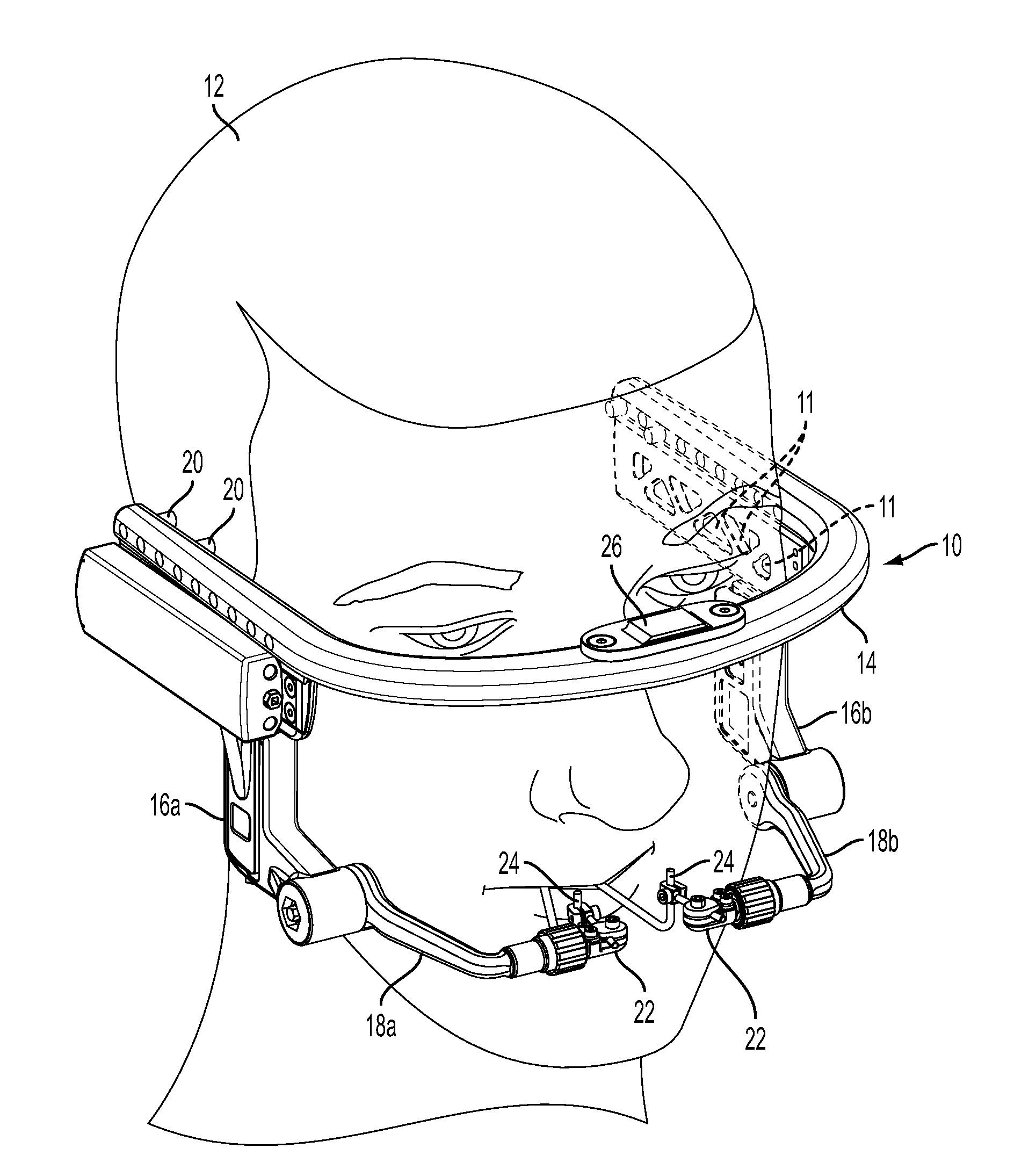
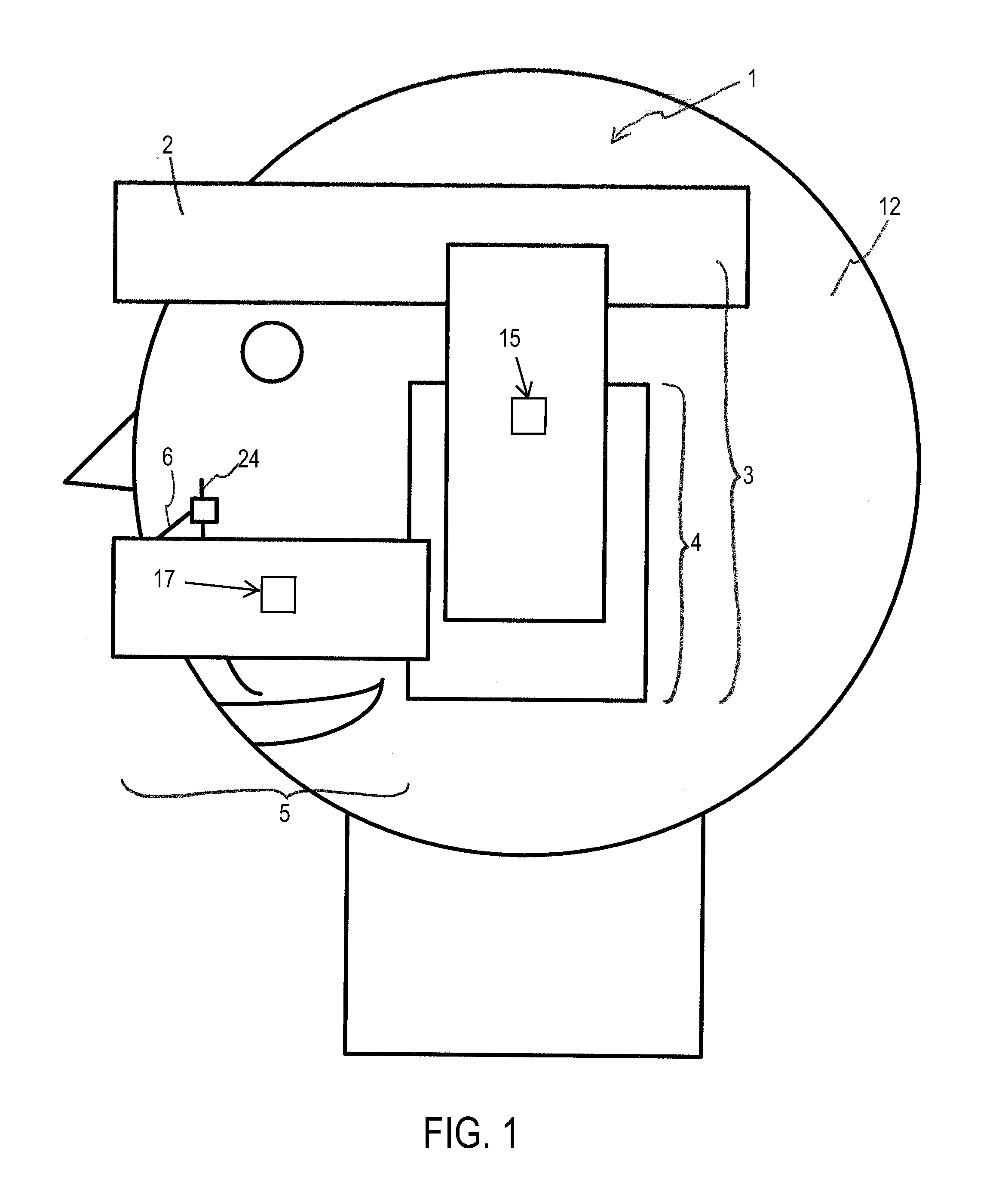
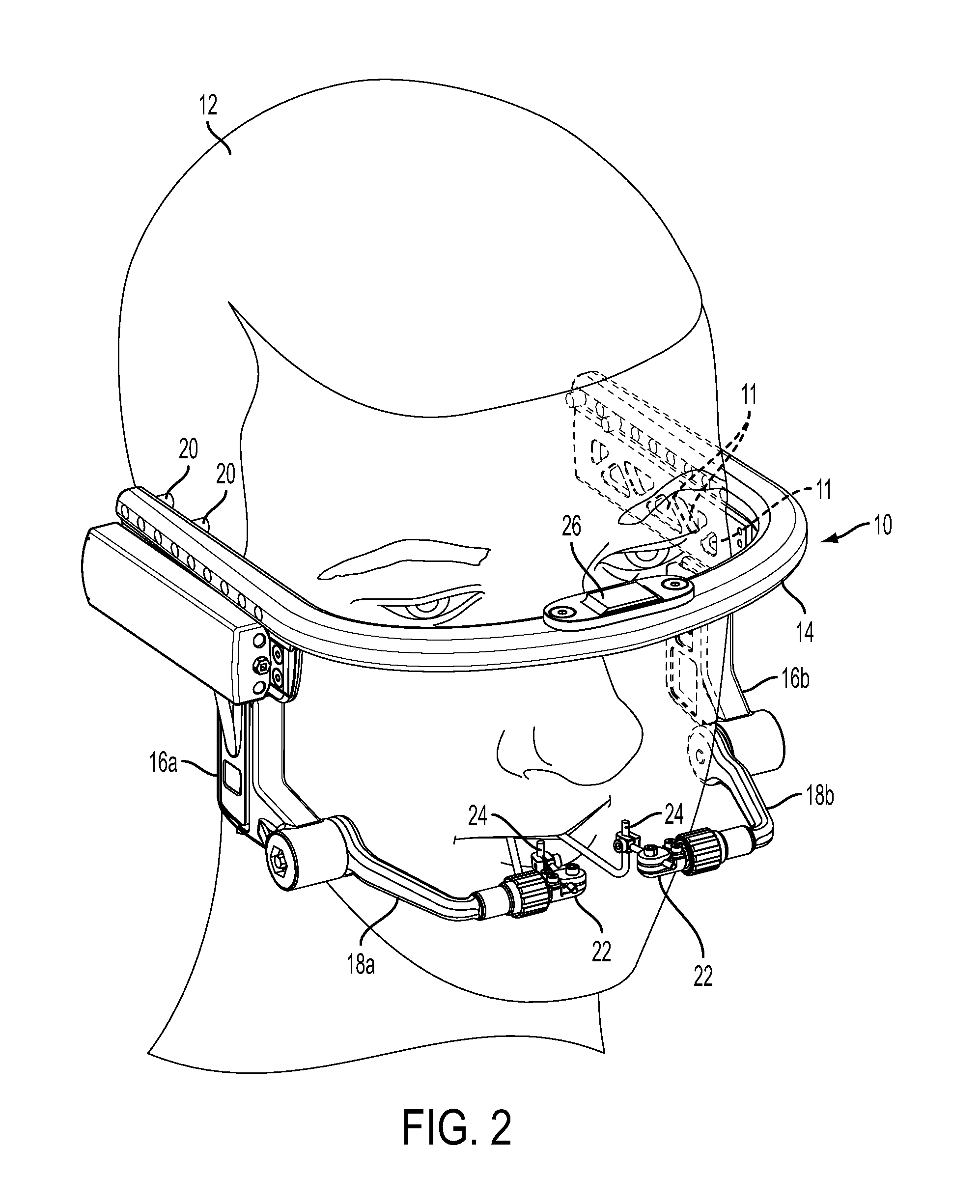
[0061]FIG. 1 depicts a representational, side view illustration of an example external distraction apparatus 1 in accordance with an embodiment of the present disclosure. The external distraction apparatus 1 may be used to correct any number of craniofacial deformities through precise, multi-dimensional movement of a portion of the craniofacial skeleton in a prescribed direction over a prescribed magnitude (distraction vector). For example, depending upon the configuration, the external distraction apparatus 1 may perform distraction movements in 3 dimensions (i.e., 3 components of translation) with 3 axes of rotation (i.e., 3 components of rotation) to be moveable in 6 degrees of freedom. In some embodiments, the device may be configured to perform distraction movement in select degrees of freedom. The apparatus 1 may, for example, be used to correct various congenital craniofacial defects, trauma induced facial deformities, etc.

[0062]The external distraction apparatus 1 includes a...


PUM


Abstract

An external distraction apparatus for performing a craniofacial distraction is disclosed. The external distraction apparatus may comprise a stationary member. The stationary member may be configured to be affixed to a head of a patient. The external distraction apparatus may also comprise laterally disposed distractors. The laterally disposed distractors may extend inferiorly from the stationary member and be moveable relative to the stationary member. The external distraction apparatus may comprise a motor and controller. The motor may be powered with the controller to perform a craniofacial distraction in an automated fashion.

Description

BACKGROUND[0001]1. Field of Disclosure[0002]The present disclosure relates to distraction osteogenesis. More specifically, the present disclosure relates to craniofacial distraction osteogenesis.[0003]2. Background Information[0004]Distraction osteogenesis was first introduced at the turn of the 20th century as a process for lengthening long bones. Generally, the process involves performing a corticotomy or osteotomy and then separating (distracting) the resulting pieces of bone such the new bone forms in the gap. The pieces of bone are separated at a rate which does not lead to fibrous non-union as the bone fills in the gap, but also does not allow for bone union until the pieces have been distracted fully along the desired vector. After distraction along the desired vector a consolidation period is generally allotted for during which the bone remodels into a more mature state and the surrounding soft tissues acclimate to their new positions and lengths.[0005]In its infancy, compli...

Claims


Application Information

Patent Timeline
IPC IPC(8): A61B17/66
CPCA61B17/66A61B17/6433A61B17/645A61B2017/00022A61B2017/00017A61B17/663A61B17/60A61B17/62A61B17/64
Inventor LANGENFELD, CHRISTOPHER C.SMITH, III, STANLEY B.ALTOBELLI, DAVID E.
Owner DEKA PROD LLP
Why Eureka
Try Eureka