
Refrigerator appliance and a door for an appliance

a technology for refrigerators and doors, applied in the field of refrigerators, can solve the problems of affecting the thermal efficiency of vacuum insulation panels, and affecting the appearance of outer panels

Inactive Publication Date: 2015-08-27
GENERAL ELECTRIC CO
View PDF6 Cites 47 Cited by
  • Summary
  • Abstract
  • Description
  • Claims
  • Application Information

AI Technical Summary

Benefits of technology

The present patent describes a refrigerator appliance with a door that includes an outer panel, a vacuum insulation panel, and a barrier layer positioned between the outer panel and the vacuum insulation panel. The barrier layer prevents air from leaking into the refrigerator while the vacuum insulation panel helps to maintain a consistent temperature. The door also has an inner liner and a handles that make it easy to grip and open and close the refrigerator. These features improve the efficiency and functionality of the refrigerator appliance.

Problems solved by technology

For example, edge effects can decrease a thermal efficiency of the vacuum insulation panel.
In addition, a shape of the vacuum insulation panel can transfer or be impressed on the outer panel such that a cosmetic appearance of the outer panel is negatively affected.
In particular, the outer panel can appear unsmooth.
Further, suitable adhesion between the vacuum insulation panel and the outer panel can be difficult if a surface finish of the vacuum insulation panel is not sufficiently smooth and includes irregularities.
Thus, a cost of the vacuum insulation panel may be increased due to the tolerances required to properly adhere the vacuum insulation panel directly to the metal outer panel.
In particular, expensive bonding methods and / or adhesives may be required to properly attach the vacuum insulation panel directly to the metal outer panel.

Method used


Image

  • Refrigerator appliance and a door for an appliance
  • Refrigerator appliance and a door for an appliance
  • Refrigerator appliance and a door for an appliance

Examples


Embodiment Construction

[0015]Reference now will be made in detail to embodiments of the invention, one or more examples of which are illustrated in the drawings. Each example is provided by way of explanation of the invention, not limitation of the invention. In fact, it will be apparent to those skilled in the art that various modifications and variations can be made in the present invention without departing from the scope or spirit of the invention. For instance, features illustrated or described as part of one embodiment can be used with another embodiment to yield a still further embodiment. Thus, it is intended that the present invention covers such modifications and variations as come within the scope of the appended claims and their equivalents.

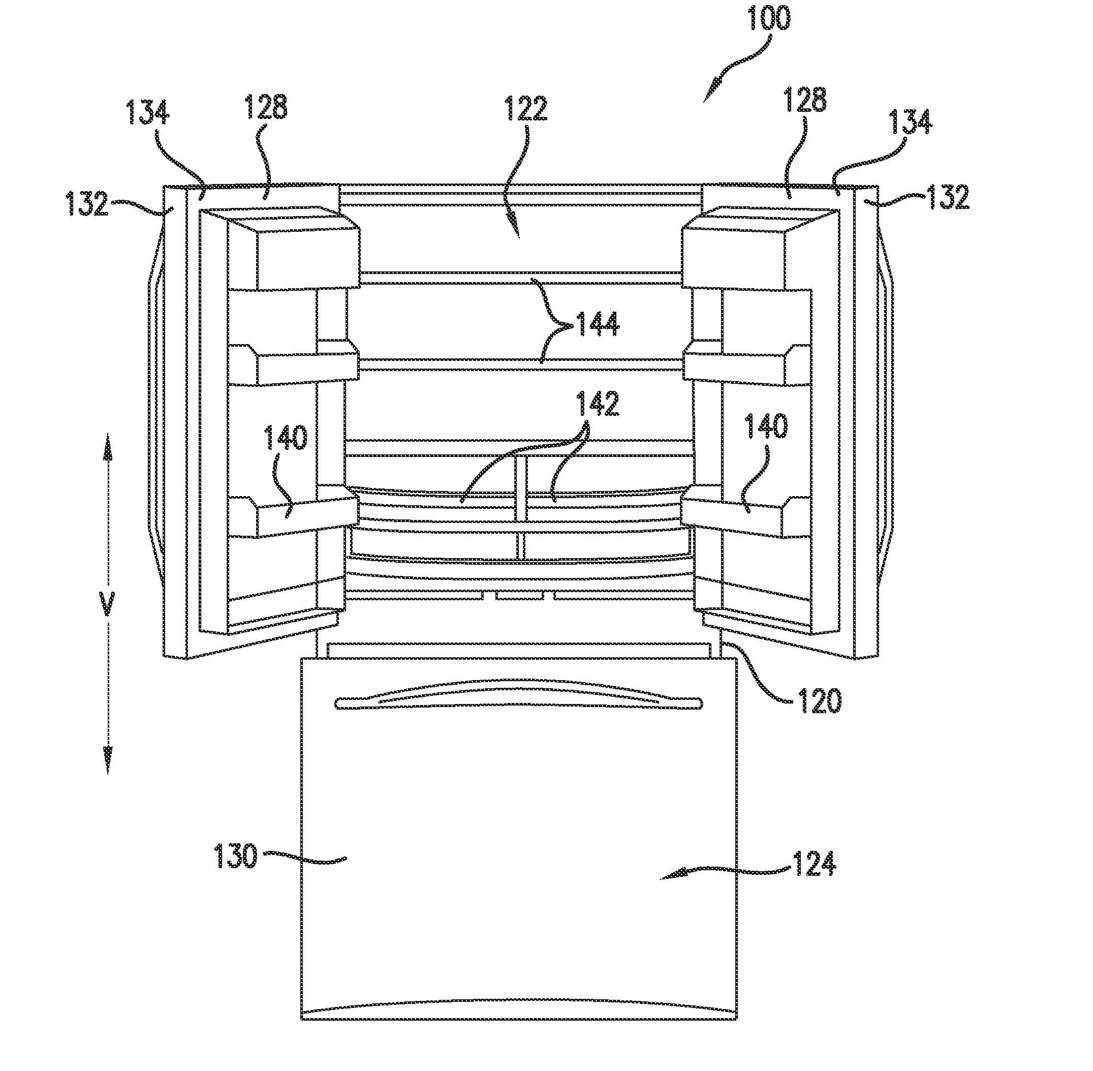
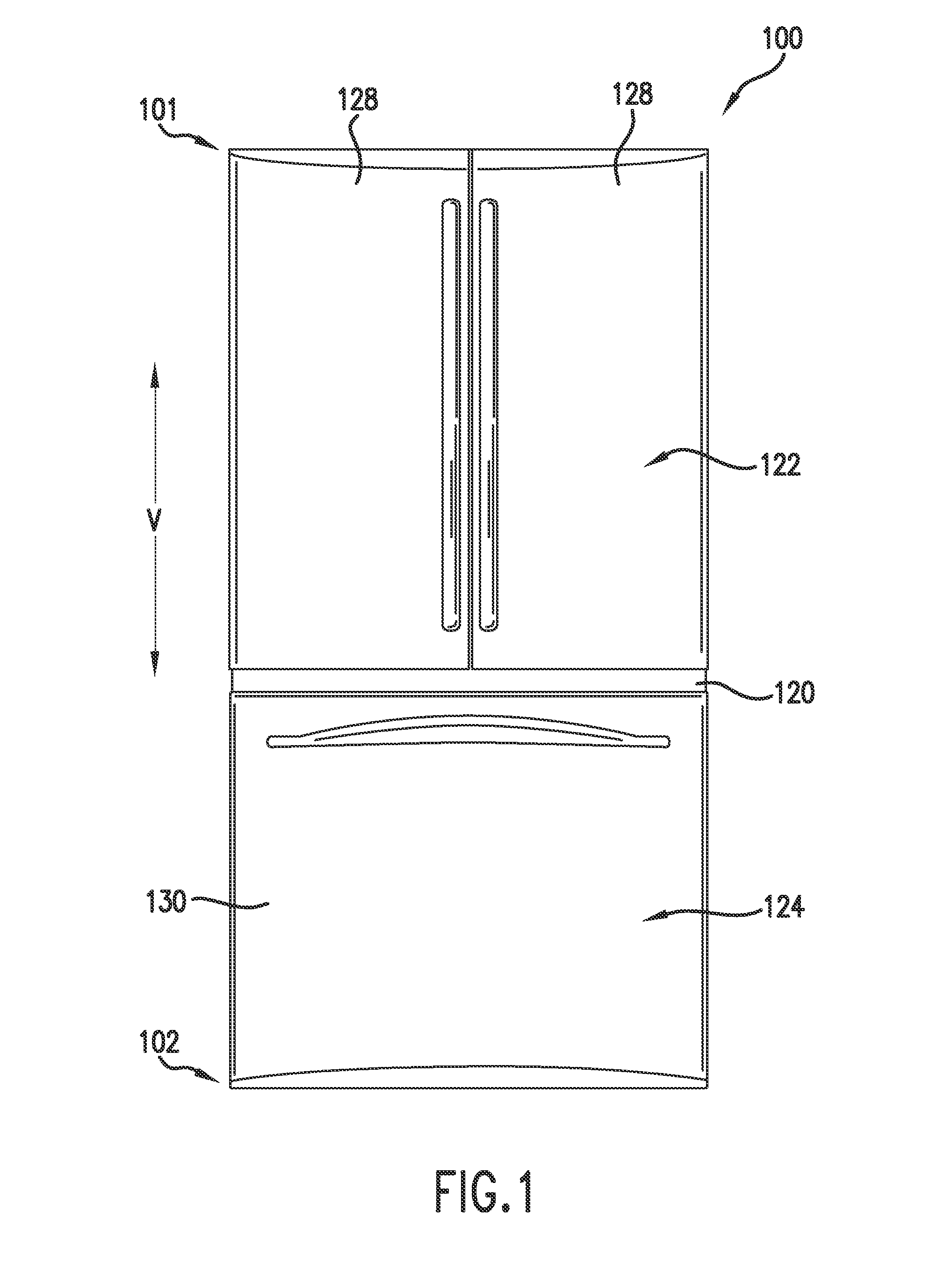
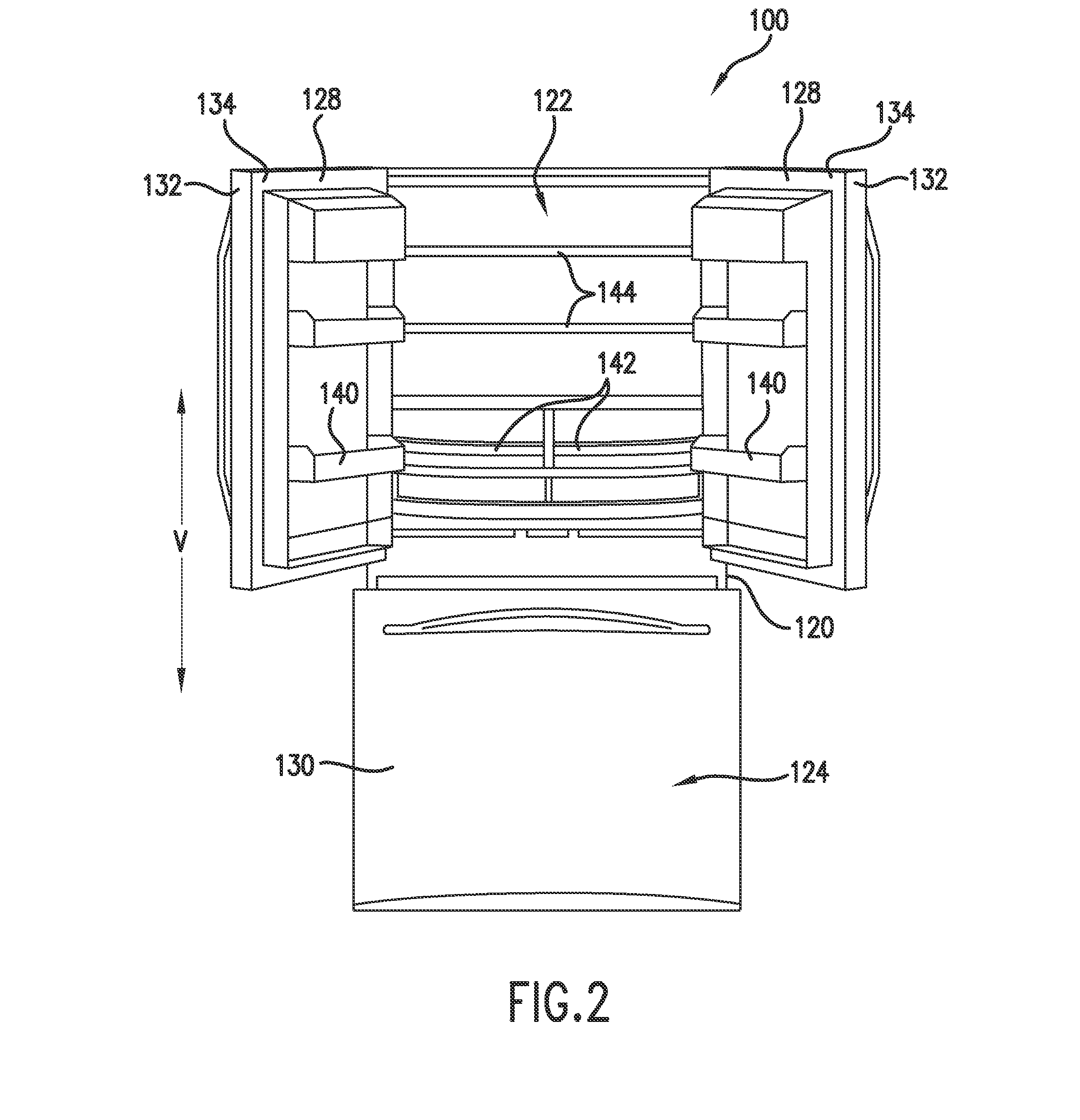
[0016]FIG. 1 provides a front, elevation view of a refrigerator appliance 100 according to an exemplary embodiment of the present subject matter with refrigerator doors 128 of the refrigerator appliance 100 shown in a closed position. FIG. 2 provides a fron...


PUM


Abstract

A door for an appliance is provided. The door of the appliance includes an outer panel with a rear surface. The door also includes a vacuum insulation panel and a barrier layer. The barrier layer is positioned between the rear surface of the outer panel and the vacuum insulation panel within the door.

Description

FIELD OF THE INVENTION[0001]The present subject matter relates generally to appliances, such as refrigerator appliances, and doors for the same.BACKGROUND OF THE INVENTION[0002]Vacuum insulation panels generally include a nearly gas-tight enclosure surrounding a rigid core, from which atmospheric gases have been at least partially evacuated. Certain refrigerator appliances include vacuum insulation panels for thermally insulating a cabinet and / or doors of the refrigerator appliances. The vacuum insulation panels can decrease heat leakage into chilled chambers of the refrigerator appliances and thereby increase an efficiency of the refrigerator appliance. To further increase the efficiency of the refrigerator appliance, the vacuum insulation panels can be utilized in combination with conventional foam or fiberglass insulation within the cabinet and doors of the refrigerator appliances. In certain refrigerator appliances, the vacuum insulation panels are attached or mounted directly t...

Claims


Application Information

Patent Timeline
Patent Type & Authority Applications(United States)
IPC IPC(8): F25D23/02
CPCF25D23/028F25D23/02F25D2201/14Y02B40/00Y10T428/231
Inventor STRAUSS, EDWARD PHILIPKYRIACOU, STEPHANOS
Owner GENERAL ELECTRIC CO
Learn More