Canopy with detachable awning

a canopy and awning technology, applied in the tent/canopy field, can solve the problems of reducing the overhead clearance within at least a certain range, and the general limitation of the canopy is not easy to achieve, and achieve the effect of stable fixing

Active Publication Date: 2015-09-10
SHELTERLOGIC
View PDF15 Cites 13 Cited by
  • Summary
  • Abstract
  • Description
  • Claims
  • Application Information

AI Technical Summary

Benefits of technology

[0009]In some configurations, said awning-connecting member comprises a leg groove and an awning tube groove; after being assembled, said awning tube being fitted to said awning tube groove and said leg groove being fitted tightly to said leg, so that said detachable awning structure is fixed to said leg. Said awning tube can be connected to said awning-connecting member by a rotating pin inserted into a fixing hole on said awning tube groove, and said awning tube being able to be rotated about the axis of said fixing hole relative to said awning-connecting member. A retention surface and a sloped entry surface can be provided at the upper portion of said awning tube groove of the awning-connecting member, said sloped entry surface helping said awning tube to slide downwards into said awning tube groove and said retention surface inhibiting or preventing the awning tube within the awning tube groove from moving out of said awning tube groove, so that said awning tube is retained in the awning tube groove in response to normal or expected forces. The cross sectional dimensions of the part of said leg groove that contacts said leg can be smaller than the cross sectional dimensions of said leg, so that said awning-connecting member is able to tightly clamp said leg without sliding downwards in response to normal or expected forces.
[0010]In some configurations, said awning tube is fixedly connected to said awning tube groove of the awning-connecting member by a fixing pin that is inserted into a fixing hole on the awning tube groove. Said awning-connecting member can be provided with an upper frame and a lower frame with flexibility that define said leg groove, and when installing, said frames being pulled open to make said awning-connecting member clamp on said leg, thus said awning-connecting member will be stably fixed on said leg due to flexibility of said frames. A tube plug can be provided at the end of said awning tube installed in the awning tube groove of the awning-connecting member, wherein a spring and a button are provided between said tube plug and bottom of said awning tube groove, a button hole being provided at the bottom of the awning tube groove, the wall of the leg that is installed in the leg groove pressing said spring and abut against said button, so that the wall of said leg tightly contacts with said frames ensuring that said awning-connecting member is fixed at a specific height of the leg without slipping off.

Problems solved by technology

However, such adjustment is typically quite limited and results in reduced overhead clearance within at least portions of the interior of the canopy.

Method used


Image

  • Canopy with detachable awning
  • Canopy with detachable awning
  • Canopy with detachable awning

Examples


first embodiment

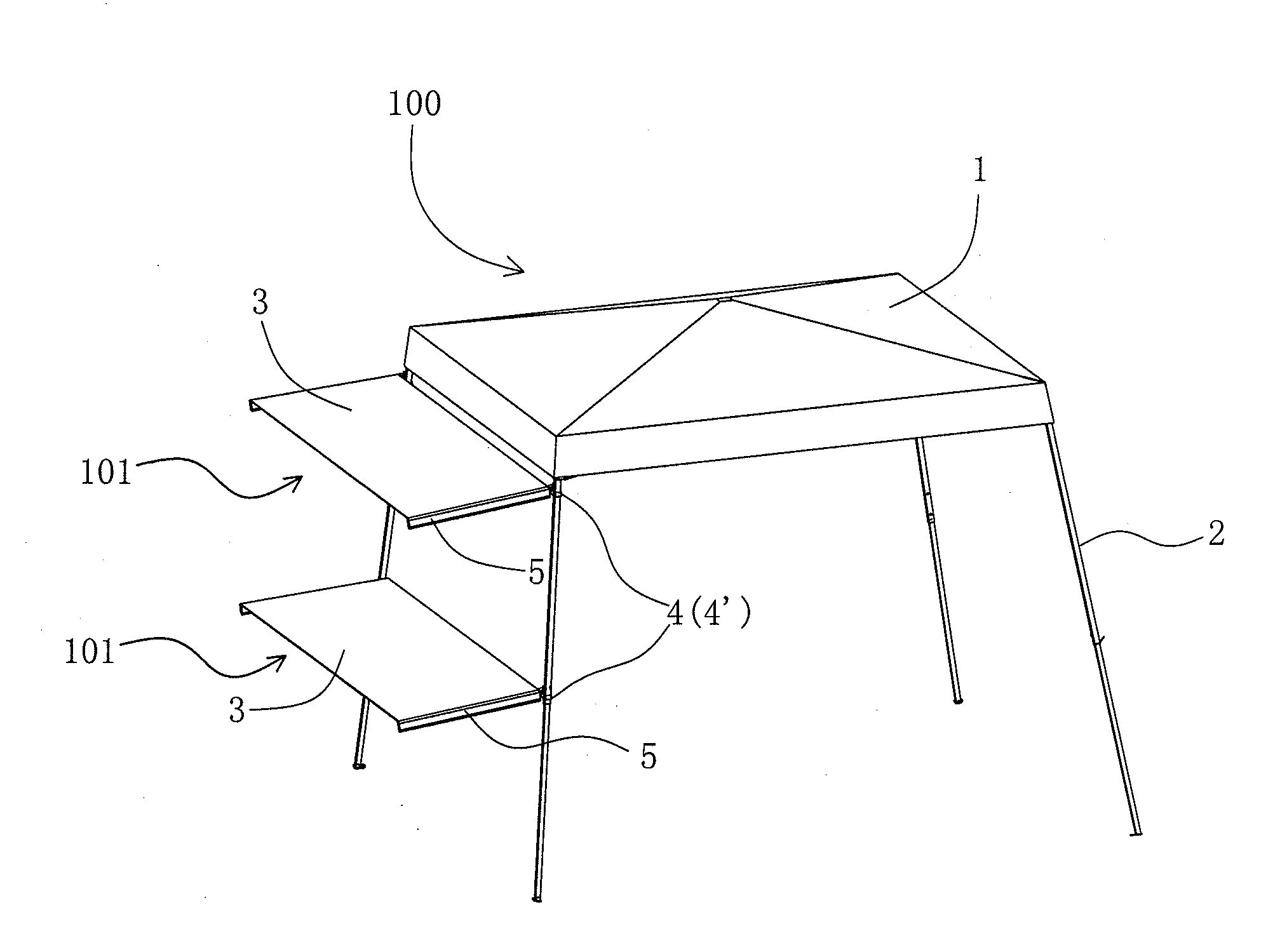
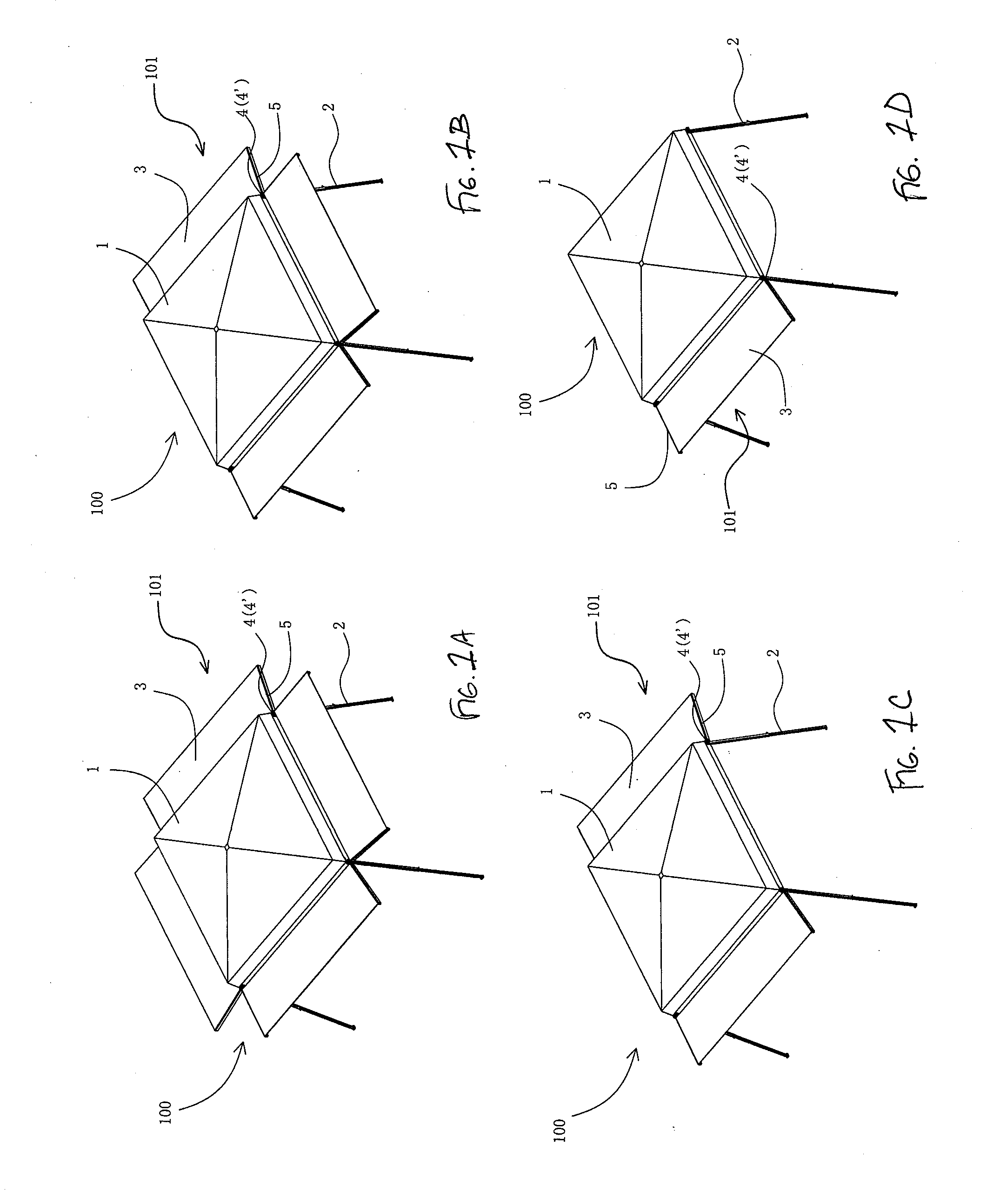
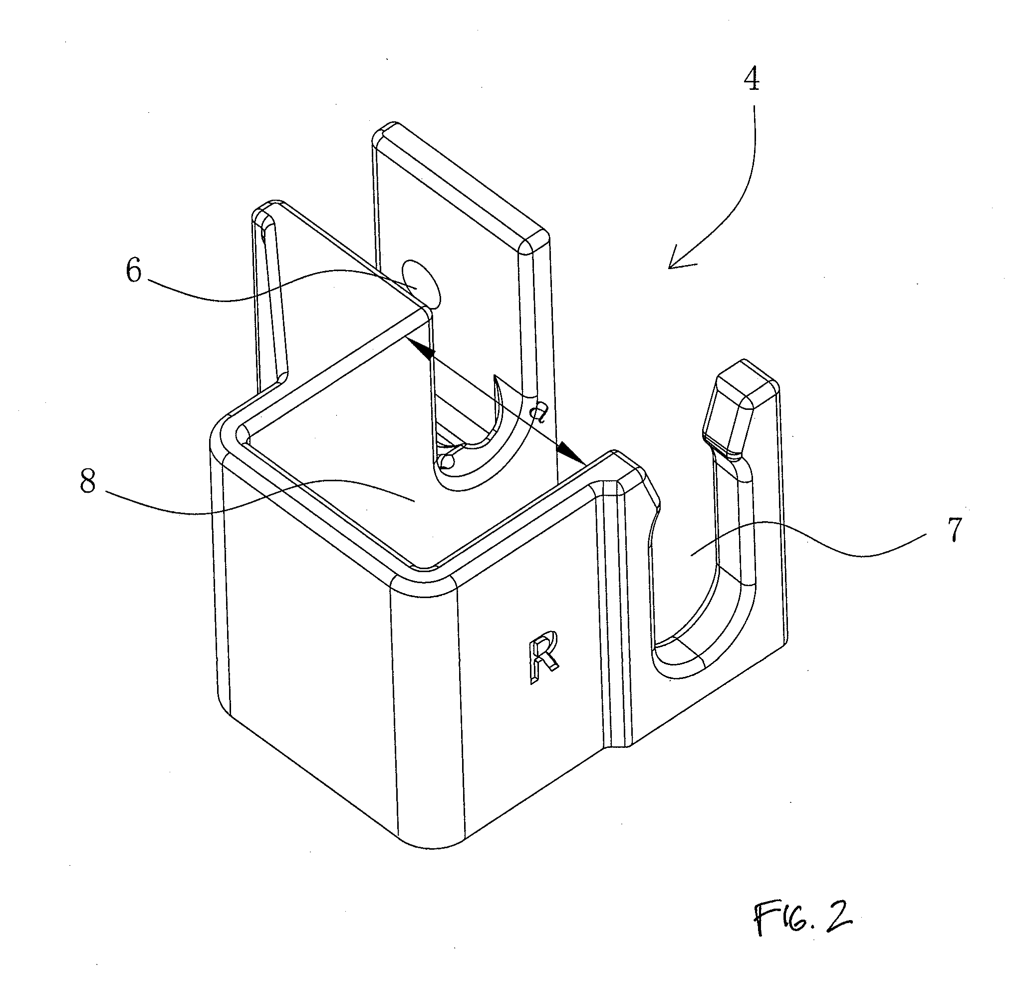
[0033]FIG. 2 is a perspective view of the connecting member 4 separate from the canopy 100. As shown, the awning connector 4 includes a leg opening 8 that removably and securably receives a support leg 2 of the canopy 100. The awning connector 4 also includes an awning support tube opening or groove 7 that selectively receives the awning support tube 5. At least one or a pair of fixing holes 6 rotatably supports the awning support tube 5, such as via a shaft, pin or fastener. Rotation of the awning support tube 5 about the rotation pin (not shown) or other support member inserted into the holes 6 allows the awning 101 to be assembled to the support leg 2 of the canopy and selectively secured in place. In some configurations, the awning 101 can be moved between two positions, such as a raised and lowered position, for example.

[0034]FIG. 3 is a front view of the overhang connector member 4 and FIG. 4 is a cross-sectional view taken along line 4-4 in FIG. 3. The connecting member 4 pre...

second embodiment

[0038]FIG. 8 is a perspective view of the connector 4′, which is a modification of the connector 4 of FIGS. 2-7. Similar to the prior embodiment, the connector 4′ includes a leg opening 8′, awning support tube duct 7′ and awning support tube fixing holes 6′. Preferably, the awning support tube 5 is received in the duct 7′ and is attached to the connector 4′ by a fixing pin (not shown) or other suitable fastener received within the tube fixing holes 6′. Preferably, the awning connecting member 4′ is constructed of an at least somewhat elastic or resilient material, such as a relatively flexible plastic material, for example.

[0039]The awning connecting member 4′ can be mounted to the leg tube 2 via upper and lower connection arms 14 that cooperate to receive and engage the leg tube 2. Preferably, the upper and lower connection arms 14 can deflect to permit engagement of the connecting member 4′ with the tent leg tube 2 and then resiliently return toward a relaxed position and / or towar...


PUM


Abstract

A tent, such as a collapsible canopy, having removable awning structures. In some embodiments, the awning structure includes a detachable connection member, an awning tube coupled to the connection member and an awning fabric or other suitable awning body. The awning cloth can be fixed on the awning tube, such as extending between a pair of awning tubes. When the intensity or direction of the outdoor environment light/precipitation changes, the removable awning structures may be deployed as desired to increase or adjust the shade area according in the desired direction to flexibly meet shade or storm requirements.

Description

INCORPORATION BY REFERENCE TO ANY PRIORITY APPLICATIONS[0001]Any and all applications for which a foreign or domestic priority claim is identified in the Application Data Sheet as filed with the present application are hereby incorporated by reference herein and made a part of the present disclosure.BACKGROUND[0002]1. Field[0003]The embodiments relate to a tent, canopy or other structure and, specifically, to a removable awning arrangement for such a tent, canopy or other structure.[0004]2. Description of the Related Art[0005]Tents or canopies, such as collapsible canopies, are often used in to provide shade or rain protection outdoors. In existing canopies, a small amount of height adjustment of the roof of the tent structure is provided by height adjustment of the support legs. Users can adjust the individual support legs to different heights to achieve an angled position of the roof of the tent structure to address sun, wind or rain that is directed at an angle and not sufficient...

Claims


Application Information

Patent Timeline
Patent Type & Authority Applications(United States)
IPC IPC(8): E04H15/58
CPCE04H15/58E04H15/00E04H15/64
Inventor LOVLEY, II, JACK B.
Owner SHELTERLOGIC
Why Eureka
Try Eureka