
Terminal for detecting an optically invisible network, installation comprising such a detection terminal, and method for detecting an optically invisible network

Active Publication Date: 2015-10-01
SOC PLYMOUTH FR
View PDF2 Cites 2 Cited by
  • Summary
  • Abstract
  • Description
  • Claims
  • Application Information

AI Technical Summary

Benefits of technology

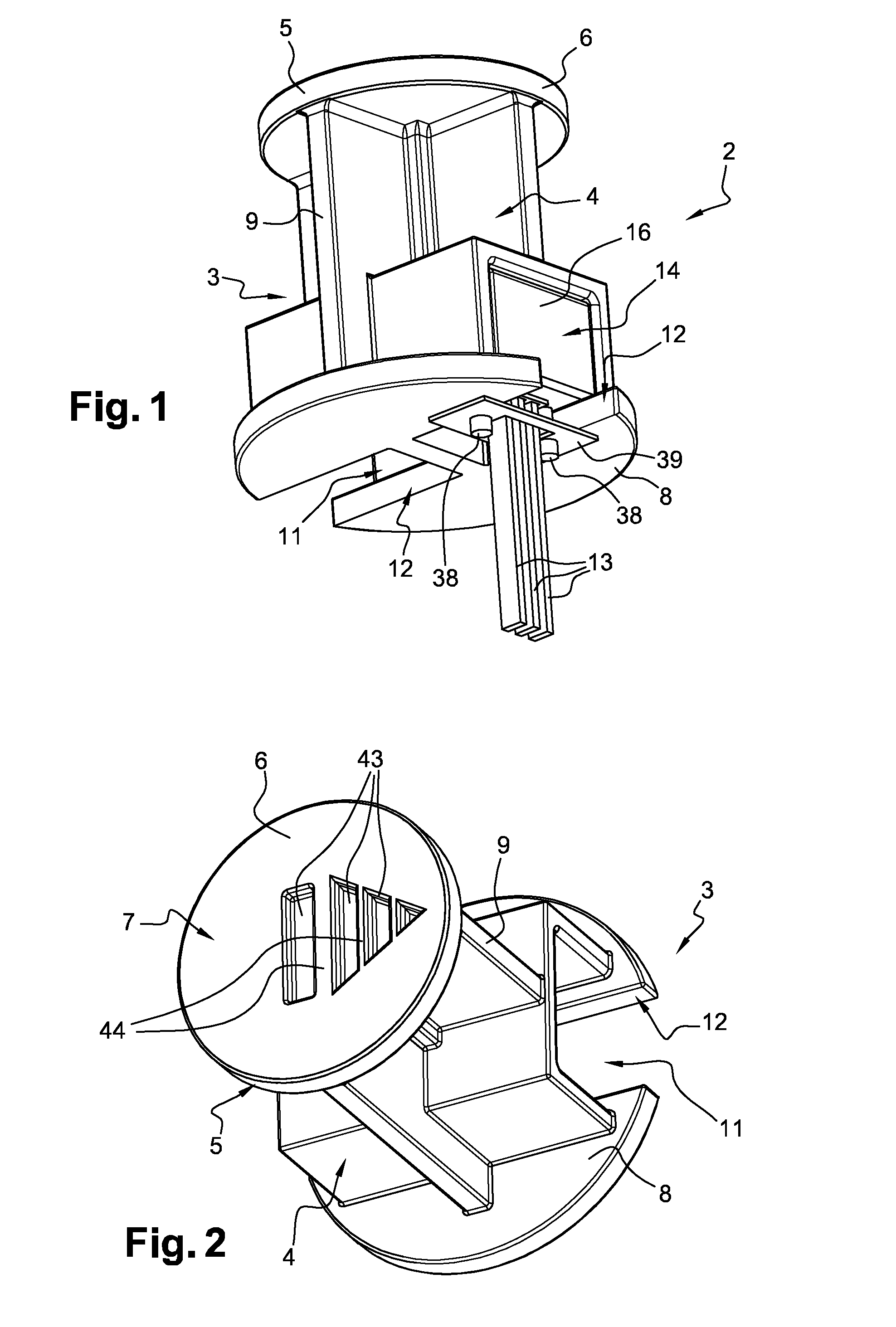
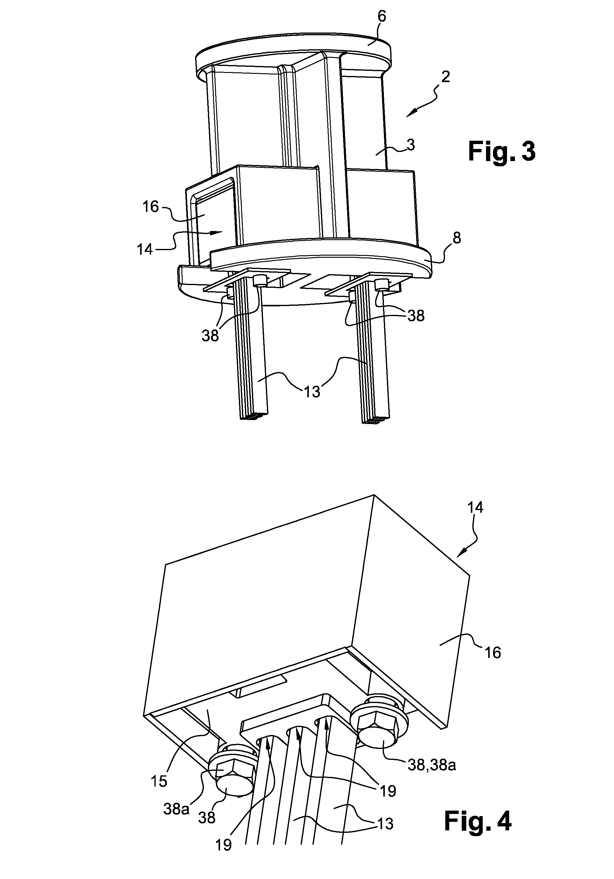
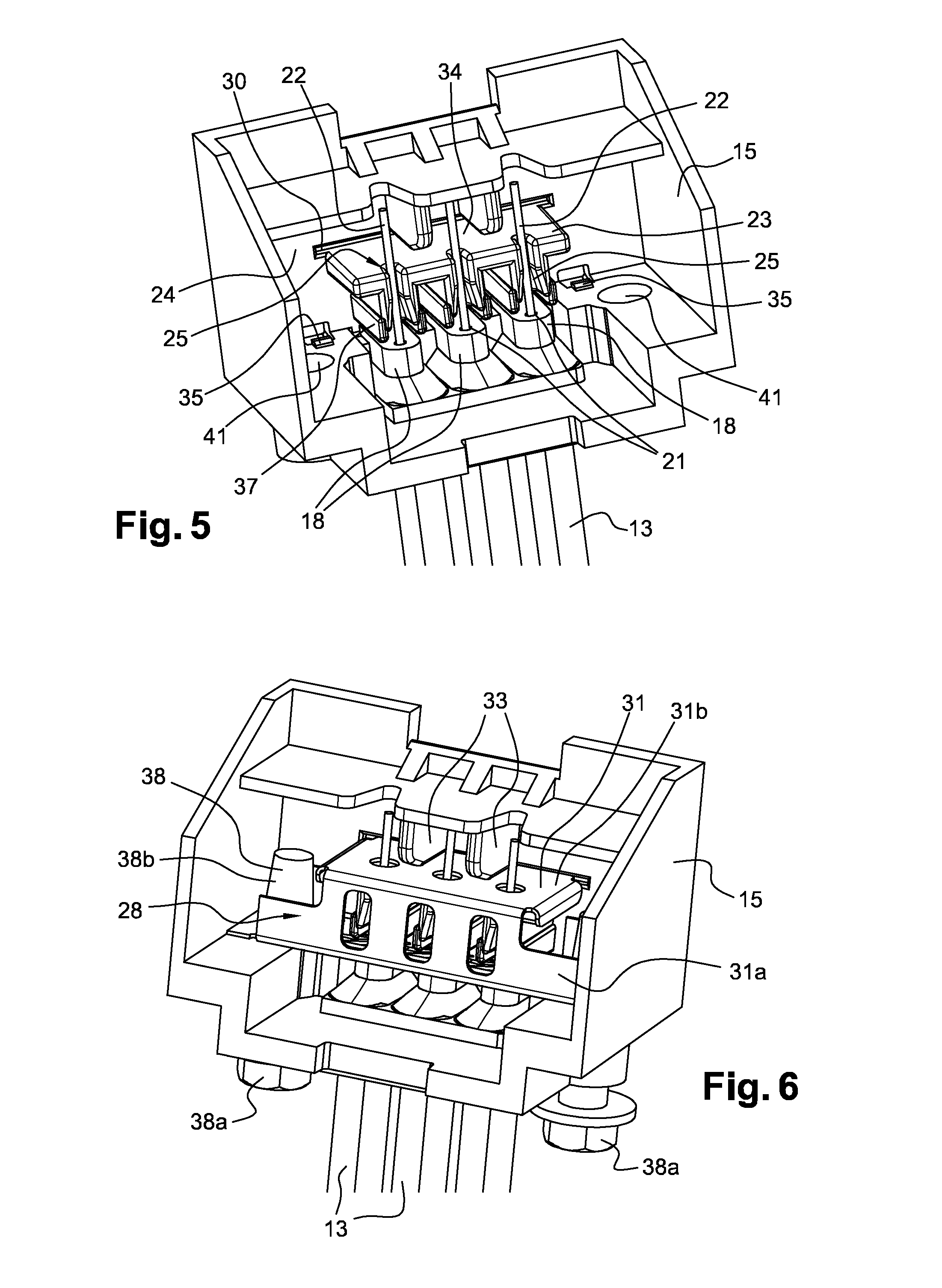
The invention is a detection terminal that allows easy and quick detection of optically invisible networks, such as gas, electricity, optical fibers, and water networks. The detection terminal is simple in structure and economical, and it does not require intrusion into any closed premises or environment, which ensures complete reliability of the detection. The detection terminal has a protective portion that makes the connection means inaccessible to the public, thereby avoiding any risk of damage. Moreover, the detection terminal can be easily located near the gas or electricity metering boxes and electrical cabinets, improving the security of the detection. The connection element comprises clamping means that allow quick and easy fixation of electrically conductive wires, without requiring any tool.

Problems solved by technology

The drawback of such an arrangement of the connection casings lies in the fact that access to the inside of a technical gallery, a manhole or a wall box is generally prohibited to the unauthorized public.
Consequently, the detection of a network may prove to be difficult when the connection casings are disposed inside of technical galleries, manholes or wall boxes.
Nonetheless, such an arrangement of the connection casings could generate degradations thereof thereby preventing any later detection of the corresponding network.

Method used


Image

  • Terminal for detecting an optically invisible network, installation comprising such a detection terminal, and method for detecting an optically invisible network
  • Terminal for detecting an optically invisible network, installation comprising such a detection terminal, and method for detecting an optically invisible network
  • Terminal for detecting an optically invisible network, installation comprising such a detection terminal, and method for detecting an optically invisible network

Examples


second embodiment

[0133]FIG. 11 represents a detection terminal 2 according to the invention which differs from the one represented in FIGS. 1 to 10 essentially in that the fixing portion 4 is devoid of any base and includes one single housing 11. The detection terminal 2 represented in FIG. 11 is more particularly intended to be fixed on a wall 48, as is schematized in FIG. 13, and thereby forms a wall detection terminal.

third embodiment

[0134]FIG. 12 represents a detection terminal 2 according to the invention which differs from the one represented in FIG. 11 essentially in that the housing 11 opens opposite to the protective plate 6.

[0135]According to an implementation variant of the detection method according to the invention schematized more particularly in FIG. 14, the electrically conductive wire 13 may be electrically connected to an electromagnetic clamp 49 which is disposed around a portion of the optically invisible network 45 and which is shaped to induce, when the detection terminal 2 is in use, that is to say when a current generator is coupled to the protective portion 5 of the latter, an electric current in an electrically conductive element 51 extending at least partially along the optically invisible network 46. Advantageously, the electrically conductive element 51 forms at least partially the optically invisible network 46 when the latter is an electrical network.

[0136]It goes without saying that ...


PUM


Abstract

This detection terminal (2) includes a fixing portion (4) intended to be fixed in a structure, an electrically conductive protective portion (5) secured to the fixing portion (4) and arranged to protect the fixing portion (4), the protective portion (5) being arranged to be accessible from the outside of the structure so as to allow the injection of an electric signal, and connection means intended to connect propagation means capable of propagating an electric signal along the optically invisible network, the connection means being connected to the protective portion (5) so as to hold, when in use, an electrical continuity between the protective portion (5) and the propagation means.

Description

TECHNICAL FIELD[0001]The present invention concerns a terminal for detecting an optically invisible network, such as a gas, electricity or water network, an installation comprising such a detection terminal, and a method for detecting an optically invisible network using such a detection terminal.BACKGROUND[0002]For saving time and costs but also for safety reasons, it is important to be able to detect the presence of an optically invisible network, and to locate it with precision, without digging the ground or destroying structures, upon later works.[0003]Several methods may be used for carrying out the detection of optically invisible networks.[0004]The electromagnetic detection is the most used method. This electromagnetic detection may be performed using electromagnetic detectors based on the active detection of an electromagnetic signal.[0005]There is known an active detection method which comprises injecting, by means a current generator, an electric signal in an electrically ...

Claims


Application Information

Patent Timeline
IPC IPC(8): G01V3/02G01V3/08
CPCG01V3/08G01V3/02G01V15/00H01R4/643H01R9/2475H01R2101/00
Inventor ARNAUD, DANIELSAAD, MOUNIR
Owner SOC PLYMOUTH FR
Learn More