Mobile terminal
Active Publication Date: 2015-10-01
LG ELECTRONICS INC
4 Cites 28 Cited by
AI-Extracted Technical Summary
Problems solved by technology
This may result in a large size and a heavy weight of the wearable device.
On the contrary, in case of a wearable device manufactu...
View moreMethod used
[0055]To facilitate such communications, the wireless communication unit 110 includes one or more of a broadcast receiving module 111, a mobile communication module 112, a wireless Internet module 113, a short-range communication module 114, and a location information module 115.
[0059]The display unit 151 may have an inter-layered structure or an integrated structure with a touch sensor in order to facilitate a touch screen. The touch screen may provide an output interface between the mobile terminal 100 and a user, as well as function as the user input unit 123 which provides an input interface between the mobile terminal 100 and the user.
[0071]The glass unit 230 is provided with a frame 231 configured to be wearable on a user's head. The frame 231 may be formed in a ‘U’ shape, which extends from a front surface of a head toward two ears when mounted on the head. However, the present invention is not limited to this. That is, the frame 231 may be formed to have other shape wearable on a user's head. The frame 231 serves as a rim of glasses, substantially. The frame 231 may be formed of a flexible material so that a user can easily wear the glass unit 230.
[0072]Part of the frame 231, which contacts a user's skin, may be formed of a silicone material for enhanced wearing sensation. The rest part of the frame 231 may be formed of a metallic material, so as to function as an antenna. At least part of the metallic part may be divided into patterns, so that antennas having various purposes can be implemented.
[0085]An object of the same weight may be wearable on a head like glasses, or may be wearable on a neck like a necklace. In this case, a user feels less fatigue when he or she has worn the object on the neck. The reason is as follows. An object worn on the neck is supported by the neck and muscles inside shoulders. On the contrary, an object worn on the head like glasses is supported by ears and a nose.
[0086]Considering that, in the present invention, the main power supply unit having a large weight of an entire weight of the mobile terminal 200 is arranged in the neck band unit 210, for a user's reduced fatigue. The neck band unit 210 does not cause inconvenience in using the mobile terminal 200, even if it has a larger size and a heavier weight than the glass unit 230, because it is worn on the neck. Thus, a user's degree of fatigue can be reduced and power required by the mobile terminal 200 can be sufficiently obtained, in a case where the main power supply unit is installed at the neck band unit 210, rather than at the glass unit 230.
[0089]The glass unit 230 may be provided therein with an auxiliary power supply unit, so as to be operable even in a non-electrically connected state with the neck band unit 210. The auxiliary power supply unit is formed to have a smaller capacity than the main power supply unit. Once the neck band unit 210 and the glass unit 230 are coupled to each other, the auxiliary power supply unit may be charged with power supplied from the main power supply unit...
View moreBenefits of technology
[0018]In another embodiment of the present invention, the glass unit may further include a camera module installed at the frame. The input/output module and the camera module may be installed at opposite sides based on a central pa...
View moreAbstract
Disclosed is a mobile terminal having a differentiated structure from the conventional one. The mobile terminal includes a neck band unit configured to be wearable on a user's neck, and having a main power supply unit; and a glass unit having a frame configured to be wearable on a user's head, having an input/output module installed at the frame, and electrically-connectable to the neck band unit so as to be provided with power from the main power supply unit, wherein the neck band unit is provided with accommodation recesses formed such that at least part thereof corresponds to the frame, and wherein the glass unit is coupled to the neck band unit when two ends thereof are inserted into the accommodation recesses, respectively, and wherein the glass unit is separated from the neck band unit when the two ends thereof are withdrawn from the accommodation recesses, respectively.
Application Domain
Technology Topic
Image
Examples
- Experimental program(1)
Example
[0046]Description will now be given in detail according to exemplary embodiments disclosed herein, with reference to the accompanying drawings. For the sake of brief description with reference to the drawings, the same or equivalent components may be provided with the same or similar reference numbers, and description thereof will not be repeated. In general, a suffix such as “module” and “unit” may be used to refer to elements or components. Use of such a suffix herein is merely intended to facilitate description of the specification, and the suffix itself is not intended to give any special meaning or function. In the present disclosure, that which is well-known to one of ordinary skill in the relevant art has generally been omitted for the sake of brevity. The accompanying drawings are used to help easily understand various technical features and it should be understood that the embodiments presented herein are not limited by the accompanying drawings. As such, the present disclosure should be construed to extend to any alterations, equivalents and substitutes in addition to those which are particularly set out in the accompanying drawings.
[0047]It will be understood that although the terms first, second, etc. may be used herein to describe various elements, these elements should not be limited by these terms. These terms are generally only used to distinguish one element from another.
[0048]It will be understood that when an element is referred to as being “connected with” another element, the element can be connected with the other element or intervening elements may also be present. In contrast, when an element is referred to as being “directly connected with” another element, there are no intervening elements present.
[0049]A singular representation may include a plural representation unless it represents a definitely different meaning from the context.
[0050]Terms such as “include” or “has” are used herein and should be understood that they are intended to indicate an existence of several components, functions or steps, disclosed in the specification, and it is also understood that greater or fewer components, functions, or steps may likewise be utilized.
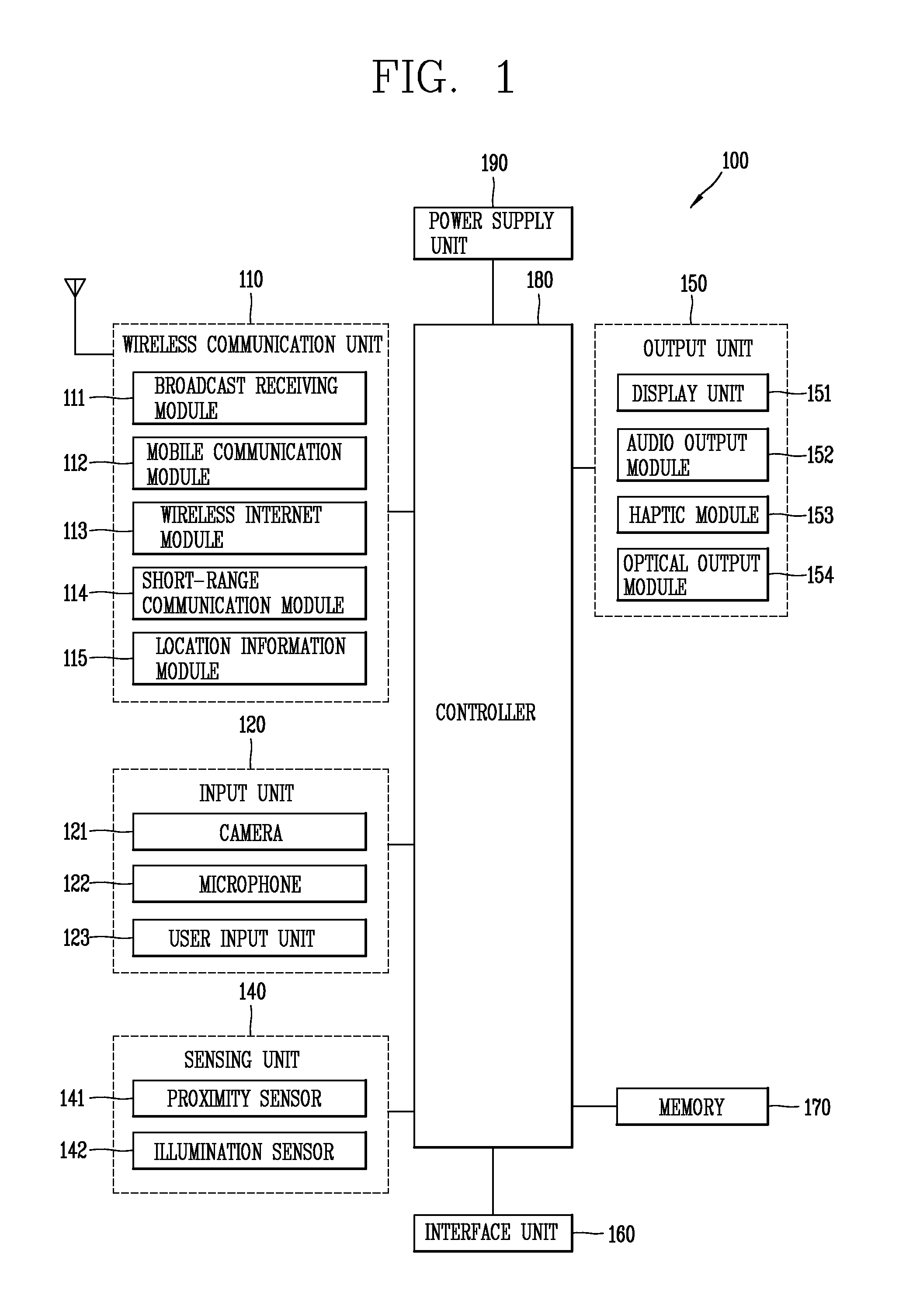
[0051]FIG. 1 is a block diagram of a mobile terminal 100 according to an embodiment of the present invention.
[0052]The mobile terminal 100 is shown having components such as a wireless communication unit 110, an input unit 120, a sensing unit 140, an output unit 150, an interface unit 160, a memory 170, a controller 180, and a power supply unit 190. It is understood that implementing all of the illustrated components is not a requirement, and that greater or fewer components may alternatively be implemented.
[0053]Referring now to FIG. 1, the wireless communication unit 110 typically includes one or more components which permit wireless communication between the mobile terminal 100 and a wireless communication system or network within which the mobile terminal is located.
[0054]The wireless communication unit 110 typically includes one or more modules which permit communications such as wireless communications between the mobile terminal 100 and a wireless communication system, communications between the mobile terminal 100 and another mobile terminal, communications between the mobile terminal 100 and an external server. Further, the wireless communication unit 110 typically includes one or more modules which connect the mobile terminal 100 to one or more networks.
[0055]To facilitate such communications, the wireless communication unit 110 includes one or more of a broadcast receiving module 111, a mobile communication module 112, a wireless Internet module 113, a short-range communication module 114, and a location information module 115.
[0056]The input unit 120 includes a camera 121 for obtaining images or video, a microphone 122, which is one type of audio input device for inputting an audio signal, and a user input unit 123 (for example, a touch key, a push key, a mechanical key, a soft key, and the like) for allowing a user to input information. Data (for example, audio, video, image, and the like) is obtained by the input unit 120 and may be analyzed and processed by controller 180 according to device parameters, user commands, and combinations thereof.
[0057]The sensing unit 140 is typically implemented using one or more sensors configured to sense internal information of the mobile terminal, the surrounding environment of the mobile terminal, user information, and the like. For example, in FIG. 1, the sensing unit 140 is shown having a proximity sensor 141 and an illumination sensor 142. If desired, the sensing unit 140 may alternatively or additionally include other types of sensors or devices, such as a touch sensor, an acceleration sensor, a magnetic sensor, a G-sensor, a gyroscope sensor, a motion sensor, an RGB sensor, an infrared (IR) sensor, a finger scan sensor, a ultrasonic sensor, an optical sensor (for example, camera 121), a microphone 122, a battery gauge, an environment sensor (for example, a barometer, a hygrometer, a thermometer, a radiation detection sensor, a thermal sensor, and a gas sensor, among others), and a chemical sensor (for example, an electronic nose, a health care sensor, a biometric sensor, and the like), to name a few. The mobile terminal 100 may be configured to utilize information obtained from sensing unit 140, and in particular, information obtained from one or more sensors of the sensing unit 140, and combinations thereof.
[0058]The output unit 150 is typically configured to output various types of information, such as audio, video, tactile output, and the like. The output unit 150 is shown having a display unit 151, an audio output module 152, a haptic module 153, and an optical output module 154.
[0059]The display unit 151 may have an inter-layered structure or an integrated structure with a touch sensor in order to facilitate a touch screen. The touch screen may provide an output interface between the mobile terminal 100 and a user, as well as function as the user input unit 123 which provides an input interface between the mobile terminal 100 and the user.
[0060]The interface unit 160 serves as an interface with various types of external devices that can be coupled to the mobile terminal 100. The interface unit 160, for example, may include any of wired or wireless ports, external power supply ports, wired or wireless data ports, memory card ports, ports for connecting a device having an identification module, audio input/output (I/O) ports, video I/O ports, earphone ports, and the like. In some cases, the mobile terminal 100 may perform assorted control functions associated with a connected external device, in response to the external device being connected to the interface unit 160.
[0061]The memory 170 is typically implemented to store data to support various functions or features of the mobile terminal 100. For instance, the memory 170 may be configured to store application programs executed in the mobile terminal 100, data or instructions for operations of the mobile terminal 100, and the like. Some of these application programs may be downloaded from an external server via wireless communication. Other application programs may be installed within the mobile terminal 100 at time of manufacturing or shipping, which is typically the case for basic functions of the mobile terminal 100 (for example, receiving a call, placing a call, receiving a message, sending a message, and the like). It is common for application programs to be stored in the memory 170, installed in the mobile terminal 100, and executed by the controller 180 to perform an operation (or function) for the mobile terminal 100.
[0062]The controller 180 typically functions to control overall operation of the mobile terminal 100, in addition to the operations associated with the application programs. The controller 180 may provide or process information or functions appropriate for a user by processing signals, data, information and the like, which are input or output by the various components depicted in FIG. 1, or activating application programs stored in the memory 170. As one example, the controller 180 controls some or all of the components illustrated in FIG. 1 according to the execution of an application program that have been stored in the memory 170.
[0063]The power supply unit 190 can be configured to receive external power or provide internal power in order to supply appropriate power required for operating elements and components included in the mobile terminal 100. The power supply unit 190 may include a battery, and the battery may be configured to be embedded in the terminal body, or configured to be detachable from the terminal body.
[0064]At least part of the above components may cooperate with each other, so as to control an operation of a mobile terminal according to various embodiments to be explained later. A method of controlling a mobile terminal may be implemented on the mobile terminal, by driving at least one application program stored in the memory 170.
[0065]A mobile terminal 200 according to the present invention, which has a differentiated structure from the conventional one, will be explained in more detail with reference to FIGS. 2 to 4.
[0066]The concept of the mobile terminal 200 may extend to a wearable device which can be worn on a user's body, from the conventional one which can be held by a user's hand. Such wearable device may include a smart watch, a smart glass, a head mounted display (HMD), etc. Hereinafter, the mobile terminal 200 implemented as a wearable device will be explained.
[0067]A wearable device may be configured to exchange data with another mobile terminal. The short-range communication module 114 (refer to FIG. 1) can recognize (or sense) a wearable device near the mobile terminal 200 (or 100). In a case where the sensed wearable device has been authenticated to communicate with other mobile terminal, the controller 180 (refer to FIG. 1) may transmit at least part of data processed in other mobile terminal, to the wearable device, through the short-range communication module 114 (refer to FIG. 1). Thus, a user can use data processed in other mobile terminal, using a wearable device. For instance, in a case where a call has been received in other mobile terminal, a user can perform a call using a wearable device. As another example, in a case where a message has been received in other mobile terminal, a user can check the received message through a wearable device.
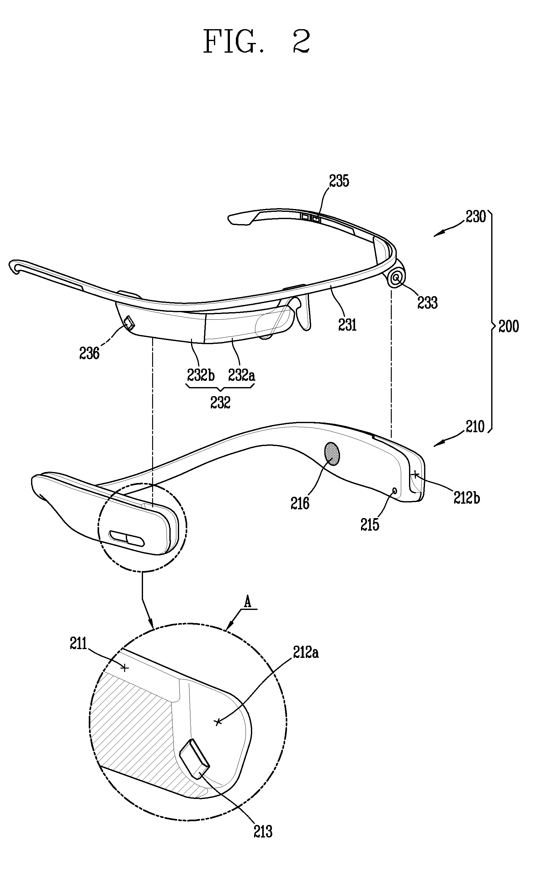
[0068]FIG. 2 is a perspective view of a mobile terminal 200 according to an embodiment of the present invention, which shows a neck band unit 210 and a glass unit 230 in a separate manner. FIG. 3 is a planar view of the mobile terminal 200 of FIG. 2, which shows a separated state between the neck band unit 210 and the glass unit 230. FIG. 4 is a perspective view of the mobile terminal 200 of FIG. 2, which shows a coupled state between the neck band unit 210 and the glass unit 230.
[0069]The mobile terminal 200 includes the neck band unit 210 worn on a user's neck like a necklace, and the glass unit 230 worn on a user's head like glasses.
[0070]The neck band unit 210 is formed to be wearable on a user's head. As shown in FIG. 2, the neck band unit 210 is formed to have a ‘U’ shape. The neck band unit 210 may be formed of a flexible material. A user may widen the neck band unit 210, and then may position his or her neck inside the ‘U’-shaped neck band unit 210. Then, if the user detaches his or her hand from the neck band unit 210, the neck band unit 210 is restored to the original state. The neck band unit 210 is worn on a user's neck through such processes.
[0071]The glass unit 230 is provided with a frame 231 configured to be wearable on a user's head. The frame 231 may be formed in a ‘U’ shape, which extends from a front surface of a head toward two ears when mounted on the head. However, the present invention is not limited to this. That is, the frame 231 may be formed to have other shape wearable on a user's head. The frame 231 serves as a rim of glasses, substantially. The frame 231 may be formed of a flexible material so that a user can easily wear the glass unit 230.
[0072]Part of the frame 231, which contacts a user's skin, may be formed of a silicone material for enhanced wearing sensation. The rest part of the frame 231 may be formed of a metallic material, so as to function as an antenna. At least part of the metallic part may be divided into patterns, so that antennas having various purposes can be implemented.
[0073]The glass unit 230 is provided with an input/output module 232 installed at the frame 231. The input/output module 232 includes an input unit and an output unit shown in FIG. 1. The input/output module 232 may include a display unit 232a and a touch input unit 232b. The display unit 232a is disposed in front of a user's eyes, and provides visual information to the user. The touch input unit 232b is configured to receive a touch input. The touch input unit 232b extends from the display unit 232a along the frame 231. The display unit 232a may be arranged on a front surface of a head, and the touch input unit 232b may be arranged on a side surface of a head.
[0074]The display unit 232a may project an image to a user's eyes using a prism. The prism may be formed to be transmissive so that a user can see not only a projected image, but also a general view (a range viewable through a user's eyes).
[0075]An image output to the display unit 232a may be overlapped with a general view. The glass type terminal 200 may provide an Augmented Reality (AR) configured to overlap a virtual image to a real image or background for a single image.
[0076]The glass unit 230 may be further provided with a camera module 233 installed at the frame 231. The camera module 233 is disposed close to at least one of a left eye and a right eye, and is configured to capture a front image. The camera module 233 can obtain a scene at which a user is looking as an image, because it is positioned close to the user's eye.
[0077]In the present invention, the input/output module 232 and the camera module 233 may be installed at opposite sides based on a central part of the frame 231, such that a weight of the glass unit 230 is prevented from being distributed to one side. However, the position of the input/output module 232 and the camera module 233 may be variable. For instance, the camera module 233 may be arranged at a central part of the frame 231.
[0078]A controller (not shown), configured to control an operation of the glass unit 230, may be mounted in the input/output module 232. The controller may operate the display unit 232a or the camera module 233, based on a user's touch input. The controller may include a micro control unit 215, for instance.
[0079]The neck band unit 210 and the glass unit 230 are formed to be coupled to or separated from each other.
[0080]The neck band unit 210 is provided with accommodation recesses 211 formed such that at least part thereof corresponds to the frame 231 of the glass unit 230. The glass unit 230 is coupled to the neck band unit 210 as two ends of the frame 231 are inserted into the accommodation recesses 211, respectively. On the contrary, the glass unit 230 is separated from the neck band unit 210 as two ends of the frame 231 are withdrawn from the accommodation recesses 211, respectively. Once the neck band unit 210 and the glass unit 230 are coupled to each other, the mobile terminal 200 is formed to have a single body. On the other hand, once the neck band unit 210 and the glass unit 230 are separated from each other, the mobile terminal 200 is formed to have two bodies.
[0081]FIGS. 2 and 3 are views illustrating the neck band unit 210 and the glass unit 230 separated from each other. The neck band unit 210 and the glass unit 230 are coupled to each other to form an annular terminal body. FIG. 4 is a view illustrating the neck band unit 210 and the glass unit 230 coupled to each other. The terminal body may be formed to have a length controllable (prolonged or shortened) in correspondence to a size of a user's neck or head.
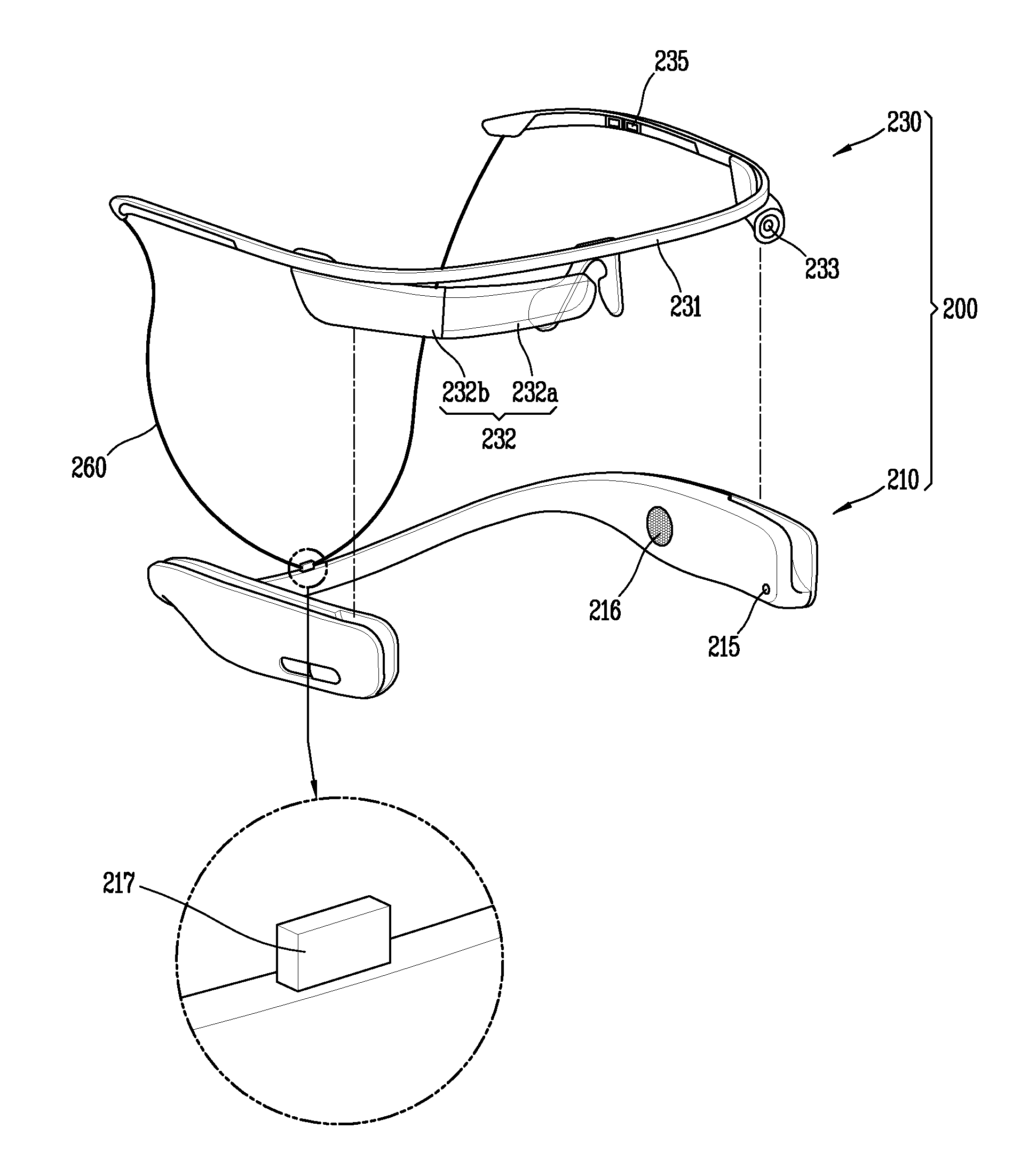
[0082]Referring to FIGS. 2 and 3, the neck band unit 210 may be provided, at two ends thereof, with a first accommodation portion 212a and a second accommodation portion 212b extending from the accommodation recesses 211. The first accommodation portion 212a is formed at one end of the neck band unit 210, and the second accommodation portion 212b is formed at another end of the neck band unit 210. As shown in FIG. 4, once the neck band unit 210 and the glass unit 230 are coupled to each other, at least part of the input/output module 232 is inserted into the first accommodation portion 212a, and at least part of the camera module 233 is inserted into the second accommodation portion 212b.
[0083]Referring to part ‘A’ in FIG. 2, the neck band unit 210 is provided with a connector 213 protruding from the first accommodation portion 212a. The input/output module 232 is provided with a port 236 corresponding to the connector 213. Once the input/output module 232 is inserted into the first accommodation portion 212a, the connector 213 is inserted into the port 236 as shown in part ‘B’ of FIG. 4. The neck band unit 210 and the glass unit 230 may be electrically-connected to each other by the connector 213 and the port 236.
[0084]In the present invention, the neck band unit 210 is provided with a main power supply unit (not shown). The main power supply unit is configured to supply power not only to the neck band unit 210, but also to the glass unit 230.
[0085]An object of the same weight may be wearable on a head like glasses, or may be wearable on a neck like a necklace. In this case, a user feels less fatigue when he or she has worn the object on the neck. The reason is as follows. An object worn on the neck is supported by the neck and muscles inside shoulders. On the contrary, an object worn on the head like glasses is supported by ears and a nose.
[0086]Considering that, in the present invention, the main power supply unit having a large weight of an entire weight of the mobile terminal 200 is arranged in the neck band unit 210, for a user's reduced fatigue. The neck band unit 210 does not cause inconvenience in using the mobile terminal 200, even if it has a larger size and a heavier weight than the glass unit 230, because it is worn on the neck. Thus, a user's degree of fatigue can be reduced and power required by the mobile terminal 200 can be sufficiently obtained, in a case where the main power supply unit is installed at the neck band unit 210, rather than at the glass unit 230.
[0087]The glass unit 230 is electrically-connected to the neck band unit 210, so as to be supplied with power from the main power supply unit mounted in the neck band unit 210. Referring to FIG. 3, the glass unit 230 is provided with charging pins 234 at two ends thereof, and the neck band unit 210 is provided with charging terminals 214 in correspondence to the charging pins 234. The charging pins 234 may be formed at the frame 231, and the charging terminals 214 may be formed at the accommodation recesses 211. As shown in FIG. 4, once the frame 231 is inserted into the accommodation recesses 211, the charging pins 234 and the charging terminals 214 come in contact with each other. The structure and the arrangement of the charging pins 234 and the charging terminals 214 are not limited to the aforementioned ones. For instance, the charging pins 234 may be formed at the neck band unit 210, whereas the charging terminals 214 may be formed at the glass unit 230.
[0088]The connector 213 and the port 236 transmit data between the neck band unit 210 and the glass unit 230. On the contrary, the charging pins 234 and the charging terminals 214 supply power from the main power supply unit to an auxiliary power supply unit (not shown). However, the structure and arrangement are not limited to the aforementioned one, which may be implemented in reverse.
[0089]The glass unit 230 may be provided therein with an auxiliary power supply unit, so as to be operable even in a non-electrically connected state with the neck band unit 210. The auxiliary power supply unit is formed to have a smaller capacity than the main power supply unit. Once the neck band unit 210 and the glass unit 230 are coupled to each other, the auxiliary power supply unit may be charged with power supplied from the main power supply unit. Power supply may be performed through the charging pins 234 and the charging terminals 214.
[0090]The mobile terminal 200 according to the present invention has a structure to prevent fatigue from being concentrated on part of a user's body, when mounted on the user. More specifically, components of the mobile terminal 200 are mounted on the neck band unit 210 and the glass unit 230 in a balanced manner. For instance, the glass unit 230 may be provided with only a minimized number of components which enable the glass unit 230 to operate, whereas the neck band unit 210 may be provided with the rest components.
[0091]The frame 231, the input/output module 232, the camera module 233, the controller, and the auxiliary power supply unit are minimized components which enable the glass unit 230 to operate, independently from the neck band unit 210. Other components, which should be installed at the glass unit 230, may be added to the glass unit 230. The components which should be absolutely installed at the glass unit 230 include a bio sensor 235 such as a photoplethysmography sensor or an electrocardiogram sensor. The photoplethysmography sensor may include an infrared LED and a light receiving portion, and the electrocardiogram sensor may include an electrode. The bio sensor 235 is configured to sense a change of blood flow or micro electricity by contacting a user's skin, thereby sensing a bio-signal transmitted through the user's skin. In the present invention, a sensor installed at the glass unit 230 is not limited to such bio sensor, but may include all types of sensors.
[0092]Of the neck band unit 210 and the glass unit 230, the glass unit 230 comes in fixed-contact with a user's skin. More specifically, the frame 231 always comes in contact with a user's skin. The frame 231 is held on a user's ears, thereby fixedly-contacting the user's head. On the contrary, the neck band unit 210 does not fixedly-contact a user's skin. Thus, the bio sensor 235 should be installed at the glass unit 230.
[0093]However, most components of the mobile terminal 200 are installed at the neck band unit 210. For instance, the neck band unit 210 may be provided at least one of the microphone 215, the audio output module 216, an ear-jack socket (not shown), a main controller (not shown) and the wireless communication unit 110 (refer to FIG. 1).
[0094]The microphone 215 may include a first microphone 215 installed at one end of the neck band unit 210, and a second microphone 215 installed at another end of the neck band unit 210. The first microphone 215 and the second microphone 215 may interwork with each other so as to remove noise rather than a user's voice.
[0095]The audio output module 216 may include a loud speaker and a bone conduction speaker. The loud speaker may be installed at one side of the neck band unit 210, and the bone conduction speaker may be installed at another side of the neck band unit 210. The bone conduction speaker is configured to transmit a sound by vibration a skull. The bone conduction speaker may be formed to be withdrawable from the neck band unit 210.
[0096]The main controller may control entire functions of the mobile terminal 200, whereas the controller of the glass unit 230 is configured to control limited functions.
[0097]The wireless communication unit 110 may include a communication module such as Bluetooth and Wi-Fi.
[0098]Such components are not always installed at the glass unit 230. Preferably, all of the microphone 215, the speaker, the ear-jack socket, the main controller and the wireless communication unit 110 are provided at the neck band unit 210.
[0099]In a case where the glass unit 230 and the neck band unit 210 are connected to each other in a wireless manner, each of the glass unit 230 and the neck band unit 210 may include the wireless communication unit 110. The glass unit 230 and the neck band unit 210 may exchange data through the wireless communication units 110. By an electrical connection between the neck band unit 210 and the glass unit 230, functions utilizable by the glass unit 230 can be extended to functions of the neck band unit 210.
[0100]In the present invention, the glass unit 230, which has a smaller size and a lighter weight than a glass type terminal, can be implemented through a distributed arrangement of components. The glass unit 230 can operate independently from the neck band unit 210, using power supplied from the auxiliary power supply unit. In order to use the glass unit 230 for a long time, the auxiliary power supply unit is preferably charged with power supplied from the main power supply unit, because the auxiliary power supply unit has a smaller capacity than the main power supply unit.
[0101]The glass unit 230 is provided with a minimized number of components required to operate the glass unit 230, whereas the neck band unit 210 is provided with most components. Thus, functions executable in the glass unit 230 may be extended by an electrical connection between the glass unit 230 and the neck band unit 210. For instance, in a case where a speaker is installed only at the neck band unit 210, if the mobile terminal 200 has been set to use only the glass unit 230 independently from the neck band unit 210, a speaker function cannot be activated by the glass unit 230. However, if the glass unit 230 and the neck band unit 210 are electrically-connected to each other, the speaker function can be activated based on an input applied through the touch input unit 232b.
[0102]Hereinafter, the mobile terminal 200, which is worn on a user in a state the neck band unit 210 and the glass unit 230 have been coupled to or separated from each other, will be explained.
[0103]FIG. 5A is a conceptual view illustrating that the neck band unit 210 and the glass unit 230 have been worn on a user's neck in a coupled state.
[0104]The neck band unit 210 and the glass unit 230 are coupled to each other, thereby forming an annular terminal body. As shown in FIG. 5A, the annular terminal body may be worn on a user's neck. While the glass unit 230 is not used, it can be stored in the neck band unit 210 worn on a user's neck, in a coupled manner. Thus, the glass unit 230 can be carried and stored, without an additional case for portability and storage.
[0105]Since the neck band unit 210 and the glass unit 230 form the annular terminal body, the mobile terminal 200 of the present invent invention can be safely stored, unless a coupled state between the neck band unit 210 and the glass unit 230 is released.
[0106]The mobile terminal 200 may further include elastic members for preventing loss of the mobile terminal 200. The elastic members are installed on inner circumferential surfaces of the accommodation recesses 211, and press the frame 231 in order to prevent the glass unit 230 from being arbitrarily separated from the accommodation recesses 211. Preferably, the elastic members may be installed on inner circumferential surfaces of the two accommodation recesses 211, thereby pressing the frame 231 at two sides. The glass unit 230 is not arbitrarily separated from the accommodation recesses 211 by the elastic members. Thus, loss of the mobile terminal 200 can be prevented.
[0107]FIG. 5B is a conceptual view illustrating that the neck band unit 210 and the glass unit 230 of the mobile terminal 200 are used in a separate manner.
[0108]FIG. 5B illustrates a preferred usage state to be implemented in the present invention. The neck band unit 210 is worn on a neck, and the glass unit 230 is worn on a head.
[0109]The neck band unit 210 and the glass unit 230 are electrically-connected to each other by any method. For instance, the neck band unit 210 and the glass unit 230 may be wirelessly paired using Bluetooth.
[0110]As shown in FIG. 5A, when a user wishes to stop using the mobile terminal 200, the user may store the glass unit 230 in the neck band unit 210 in a coupled manner.
[0111]FIG. 5C is a conceptual view illustrating that the neck band unit 210 and the glass unit 230 have been worn on a user's head in a coupled state.
[0112]A user can wear the mobile terminal 200 in a state where the neck band unit 210 and the glass unit 230 have been coupled to each other. A user can wear an annular terminal body on a head in the form of a hair band. A length of the terminal body can be controlled in correspondence to a size of a user's neck or head.
[0113]Hereinafter, an electrical connection between the neck band unit 210 and the glass unit 230 will be explained.
[0114]FIG. 6 is a conceptual view for explaining an electrical connection between the neck band unit 210 and the glass unit 230.
[0115]The mobile terminal 200 may further include a cable 250 configured to connect the neck band unit 210 and the glass unit 230 to each other in a state where the neck band unit 210 and the glass unit 230 have been separated from each other. As shown in FIG. 6, the cable 250 may connect a connector 213 of the neck band unit 210 to a port 236 of the glass unit 230.
[0116]The cable 250 may supply power to the auxiliary power supply unit from the main power supply unit, and may transmit data between the neck band unit 210 and the glass unit 230.
[0117]FIG. 7 is a conceptual view for explaining another electrical connection between the neck band unit 210 and the glass unit 230.
[0118]The neck band unit 210 is provided with a connector 217 on an outer surface thereof, the outer surface arranged at a rear region of a neck when a user has worn the neck band unit 210. The glass unit 230 is provided, at two ends thereof, with terminal portions electrically-connected to the neck band unit 210 through the connector 217. The connector 217 is connected to the two terminal portions through a cable 260 branched into two parts from the connector 217 and extending toward the terminal portions.
[0119]As aforementioned, the cable 260 may supply power to the auxiliary power supply unit from the main power supply unit, and may transmit data between the neck band unit 210 and the glass unit 230.
[0120]Unlike the configuration aforementioned with reference to FIGS. 6 and 7, the neck band unit 210 and the glass unit 230 may be wirelessly connected to each other. Each of the neck band unit 210 and the glass unit 230 may include a wireless communication unit, and the wireless communication unit may adopt a Bluetooth method. However, a wireless communication method between the neck band unit 210 and the glass unit 230 is not limited to such Bluetooth method.
[0121]Hereinafter, a structure for charging the main power supply unit will be explained.
[0122]FIGS. 8A and 8B are conceptual views each illustrating an inner structure of part ‘VIII’ shown in FIG. 4.
[0123]The main power supply unit of the neck band unit 210 may be connected to a charger by wire through a charging port (not shown), thereby being provided with power. Alternatively, the main power supply unit may be wirelessly provided with power from a wireless charger.
[0124]FIGS. 8A and 8B are views for explaining a structure to receive power in a wireless manner. The neck band unit 210 may be provided therein with wireless charging coils 218 and 219 for charging the main power supply unit by wirelessly receiving power from an external wireless charger.
[0125]FIG. 8A illustrates a wireless charging coil 218 implemented using a flexible printed circuit board (FPBC). FIG. 8B illustrates a structure where a wireless charging coil 219 has been wound on a shaft disposed in the neck band unit 210. Each of the wireless charging coils 218 and 219 may operate by being electrically-connected to a main printed circuit board (not shown) formed in the neck band unit 210.
[0126]The present invention may have the following advantages.
[0127]Firstly, the neck band unit and the glass unit may be coupled to each other or separated from each other, by a user's selection. Further, components of the mobile terminal may be mounted to the neck band unit and the glass unit in a distributed manner. Thus, a weight of the mobile terminal can be distributed to the neck band unit and the glass unit, and the degree of fatigue applied to a user wearing the mobile terminal can be reduced. Further, once the glass unit and the neck band unit are electrically-connected to each other, functions of the glass unit may be extended.
[0128]Besides, the glass unit can be used independently by being separated from the neck band unit. Further, power required by the glass unit may be supplied from the neck band unit. As a result, shortage of power, a problem occurring from the conventional wearable device, can be solved.
[0129]Further, the mobile terminal of the present invention can be carried and stored without an additional case.
[0130]As the present features may be embodied in several forms without departing from the characteristics thereof, it should also be understood that the above-described embodiments are not limited by any of the details of the foregoing description, unless otherwise specified, but rather should be construed broadly within its scope as defined in the appended claims, and therefore all changes and modifications that fall within the metes and bounds of the claims, or equivalents of such metes and bounds are therefore intended to be embraced by the appended claims.
Login to view more PUM


Description & Claims & Application Information
We can also present the details of the Description, Claims and Application information to help users get a comprehensive understanding of the technical details of the patent, such as background art, summary of invention, brief description of drawings, description of embodiments, and other original content. On the other hand, users can also determine the specific scope of protection of the technology through the list of claims; as well as understand the changes in the life cycle of the technology with the presentation of the patent timeline. Login to view more.
Login to view more Similar technology patents
Patient support device
Owner:SIEMENS HEALTHCARE GMBH
Vehicle seat control system, vehicle seat control method, and storage medium
Owner:HONDA MOTOR CO LTD
Method for producing porous silicone sheet, frozen body, and porous silicone sheet rolled-body
InactiveUS20180072031A1Prevent fracturePrevent weightSynthetic resin layered productsFlat articlesPolymer chemistryImpurity
Owner:NITTO DENKO CORP
Overtaking assisting method and system for vehicle
ActiveCN107097773AReduce fatigueReduce potential riskExternal condition input parametersPotential riskDriver safety
Owner:GEELY AUTOMOBILE INST NINGBO CO LTD +1
Classification and recommendation of technical efficacy words
- Reduce fatigue
- Prevent weight
Dictation selection
ActiveUS8032372B1Reduce fatigueReduce physical stressNatural language translationComputer-assisted medical data acquisitionMedical transcriptionFeature set
Owner:DELIVERHEALTH SOLUTIONS LLC
Electrosurgical instrument with adjustable utility conduit
ActiveUS20130006236A1Improve performanceReduce fatigueSurgical needlesSurgical instruments for heatingMotion resistanceEngineering
Owner:MEGADYNE MED PROD INC US
Locking hinge connector apparatus
Owner:BLACKMAN GARY PALMER +1
Methods and devices for reducing elbow pain and arm fatigue for poker players when playing poker
Owner:SCOTT MICHAEL A +1
Pedal device with function of adjusting pedal effort and hysteresis
ActiveUS20080276750A1Reduce fatigueSatisfy preferencesControlling membersMechanical apparatusDriver/operatorEngineering
Owner:DONG HEE IND
Patient support device
Owner:SIEMENS HEALTHCARE GMBH
Method for producing porous silicone sheet, frozen body, and porous silicone sheet rolled-body
InactiveUS20180072031A1Prevent fracturePrevent weightSynthetic resin layered productsFlat articlesPolymer chemistryImpurity
Owner:NITTO DENKO CORP