Method and apparatus for transmitting signals in an optical transport network

a technology of optical transport network and transmission method, applied in the field of telecommunications, can solve the problems of complex multiplexing structure, complex implementation and management of network elements, and increasing complexity of multiplexing structur

Inactive Publication Date: 2015-10-15
ALCATEL LUCENT SAS
View PDF11 Cites 4 Cited by
  • Summary
  • Abstract
  • Description
  • Claims
  • Application Information

AI Technical Summary

Benefits of technology

[0007]In particular, a transport signal which has a frame structure referred to as Optical Transport Units will be transmitted through an Optical Transport Network domain. Each Optical Transport Unit contains at least one Optical Data Unit of fixed size with an overhead section and a payload section. A edge network node of the Optical Transport Network domain receives the transport signal and remaps the at least one Optical Data Unit of fixed size into a domain-internal lower order Optical Data Unit of flexible size, which size is configurable in granularity of predefined tributary slots of

Problems solved by technology

Due to addition of new client types, such as GbE and 10 GbE, the multiplexing structure became more and more complex o

Method used


Image

  • Method and apparatus for transmitting signals in an optical transport network
  • Method and apparatus for transmitting signals in an optical transport network
  • Method and apparatus for transmitting signals in an optical transport network

Examples


Embodiment Construction

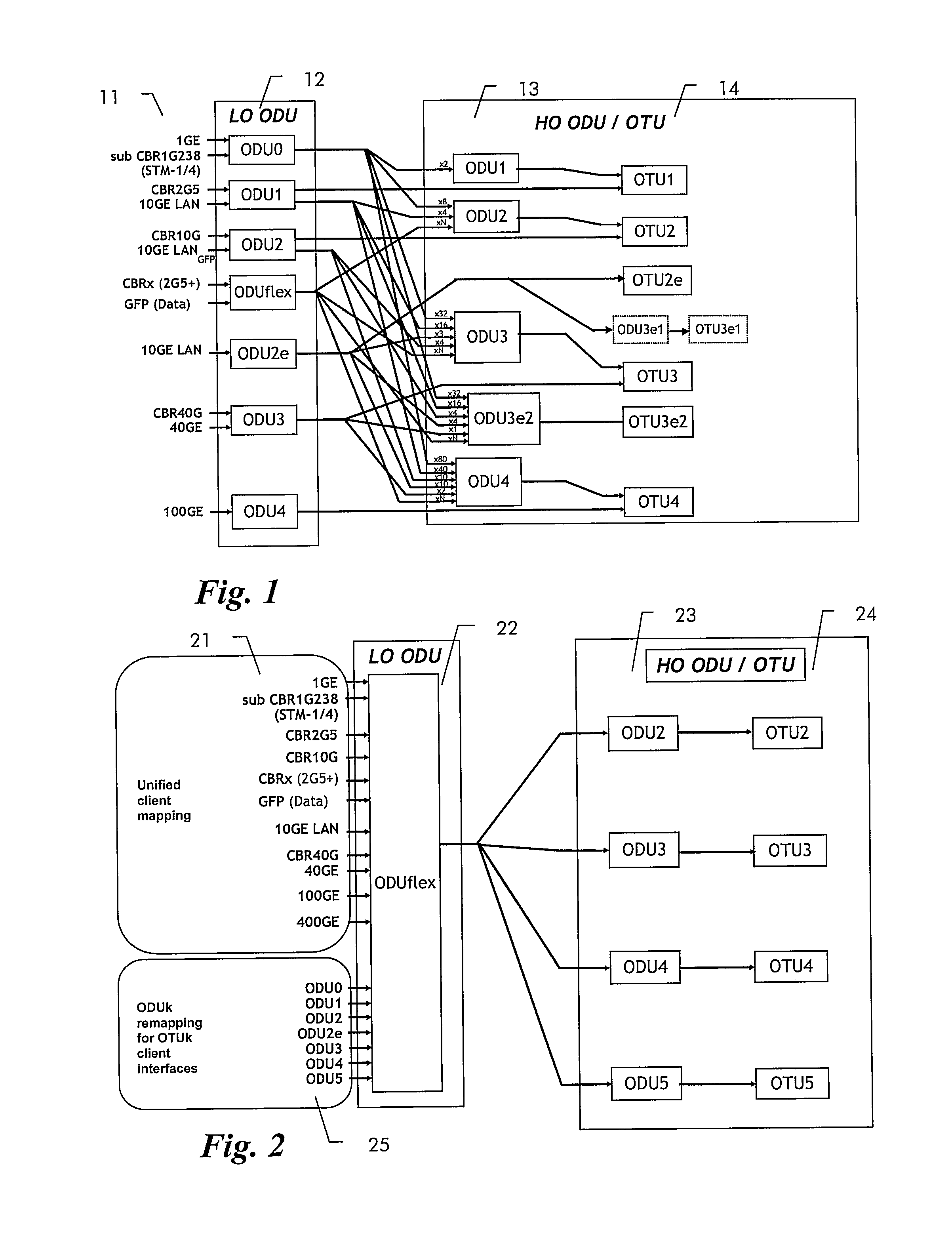
[0015]FIG. 1 shows an overview of the multiplexing structure currently used in G.709 networks. Different mappings are defined for different client signals 11 into different type of lower order ODUk 12, which can then be multiplexed into different size higher order ODUk 13 and then synchronously mapped into corresponding OTUk frames 14. This multiplexing structure will even be complicated by the future introduction of a next higher ODUk rate of approximately 400 Gb that will then be termed ODUs.

[0016]To simplify this multiplexing hierarchy, the inventor proposes to map all kind of client signals into lower order ODUflex and remap existing ODUk into order ODUflex.

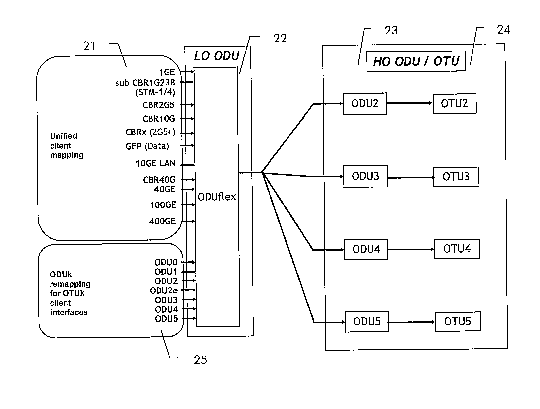
[0017]The resulting multiplexing hierarchy is shown schematically in FIG. 2. All client signals 21, independent of their type and origin will be mapped into ODUflex 22. Existing ODUk 25 will be re-mapped into ODUflex 22. ODUflex 22 will then be multiplexed and mapped into a higher order ODUk 23 corresponding to the line rate ...


PUM


Abstract

An exemplary method and apparatus are provided for a remapping of Optical Data Units of fixed size into lower order Optical Data Units of flexible size. More particularly, a transport signal which has a frame structure referred to as Optical Transport Units may be transmitted through an Optical Transport Network domain. Each Optical Transport Unit contains at least one Optical Data Unit of fixed size with an overhead section and a payload section. An edge network node of the Optical Transport Network domain receives the transport signal and remaps the at least one Optical Data Unit of fixed size into a domain-internal lower order Optical Data Unit of flexible size. Within the Optical Transport Network domain, the remapped domain-internal lower order Optical Data Unit of flexible size is transmitted as payload of a domain-internal higher order Optical Data Unit of fixed size.

Description

FIELD OF THE INVENTION[0001]The present invention relates to the field of telecommunications and more particularly to a method and related apparatus for transmitting optical signals in an Optical Transport Network.BACKGROUND OF THE INVENTION[0002]The ITU has defined in ITU-T G.709 the signals format and interfaces of the Optical Transport Network (OTN). The basic frame structure is an Optical Transport Module of size k (OTUk), where k can be 1, 2, 2e, 3, 3e2, or 4. It contains framing and section overhead plus a bit-synchronously mapped transport entity termed Optical Data Unit of size k (ODUk). An ODUk contains a payload area plus ODUk overhead. An Optical Payload Unit (OPUk) is mapped into the payload area and carries a client signal or other lower order ODUs being time-division multiplexed. OTUk signals are asynchronous within certain specified limits of typically ±20 ppm.[0003]In an Optical Transport Network, connections are switched on ODU level. The ODU is thus the switchable ...

Claims


Application Information

Patent Timeline
IPC IPC(8): H04L12/805H04J14/02H04B10/27H04L47/36
CPCH04L47/365H04J14/02H04B10/27H04J3/1652
Inventor LOEHR, JURGEN
Owner ALCATEL LUCENT SAS
Why Eureka
Try Eureka