
Destination proposal system, destination proposal method, and storage medium for program product

a technology of destination proposal and destination, applied in the field of system to propose destinations, can solve the problem of not always proposing destinations in places

Inactive Publication Date: 2015-10-22
DENSO CORP
View PDF0 Cites 7 Cited by
  • Summary
  • Abstract
  • Description
  • Claims
  • Application Information

AI Technical Summary

Benefits of technology

The present invention is a system that proposes destinations for users based on their activity range and behavior pattern. It can search for facilities both from the user's living area and non-living area based on travel history data. This makes it easy for the user to find suitable facilities at their destination.

Problems solved by technology

The conventional application can propose destinations in a genre desired by a user, but cannot always propose destinations in places which the user can easily visit.

Method used


Image

  • Destination proposal system, destination proposal method, and storage medium for program product
  • Destination proposal system, destination proposal method, and storage medium for program product
  • Destination proposal system, destination proposal method, and storage medium for program product

Examples


first embodiment

[0044][Configuration of Destination Proposal System]

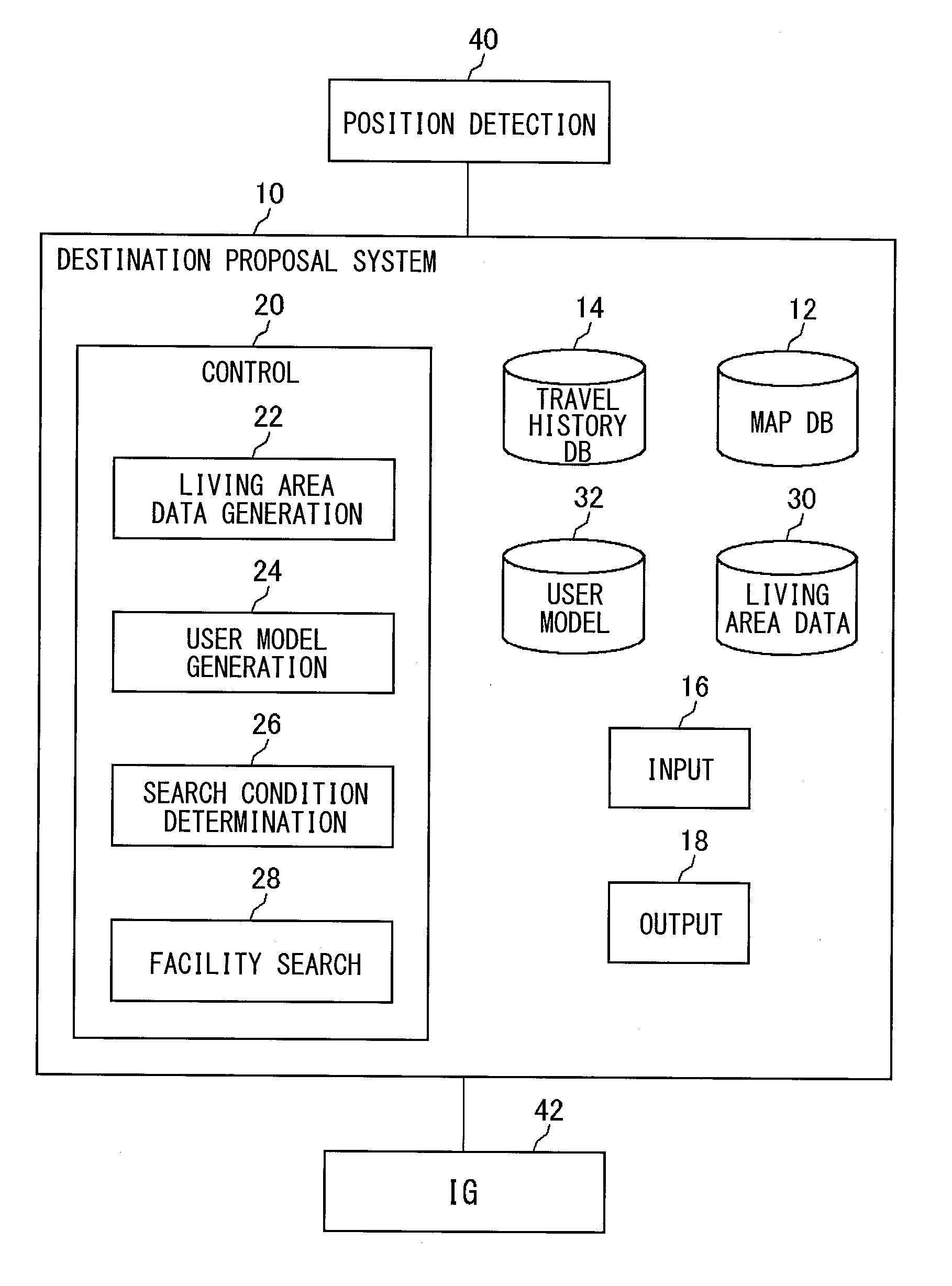
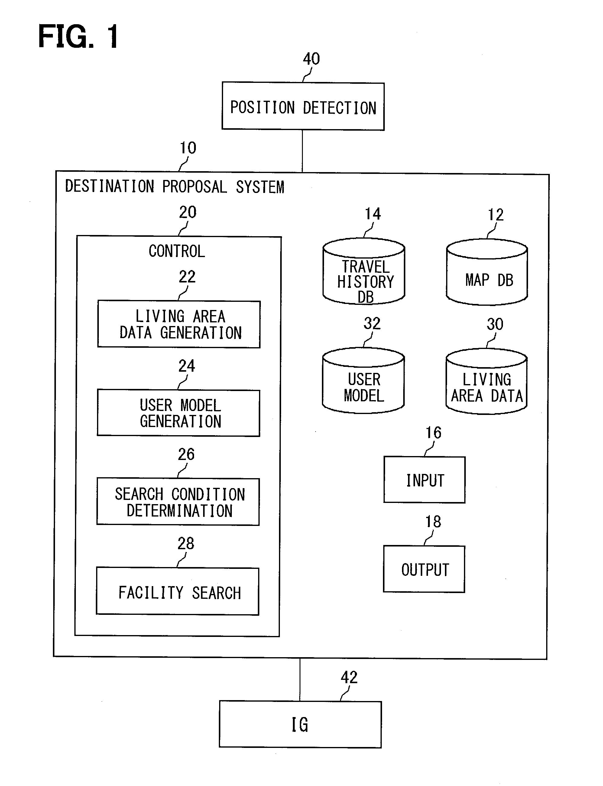
[0045]FIG. 1 illustrates a configuration of a destination proposal system 10 according to a first embodiment. The destination proposal system 10 according to the first embodiment is installed and used in a vehicle. The destination proposal system 10 includes a map database (hereinbelow, “map DB”) 12 holding map data, a travel history database (hereinbelow, “travel history DB”) 14 holding a travel history of the vehicle, an input part 16 to input a destination proposal request, an output part 18 to output destination candidates, and a control circuit 20 to search for facilities to be proposed as destinations. Note that the database is also referred to as a database storage part or a data storage part.

[0046]The destination proposal system 10 is connected to a current position detection unit 40 and an ignition key 42. The current position detection unit 40 includes a geomagnetic sensor to detect an absolute azimuth of the vehicle, a g...

second embodiment

[0095]Next, the destination proposal system 10 according to a second embodiment of the present disclosure will be described. The basic configuration of the destination proposal system 10 according to the second embodiment is the same as that of the destination proposal system 10 according to the first embodiment, however, the way of user model generation is different from that in the first embodiment.

[0096]FIG. 12 illustrates an example of the user model generated with the destination proposal system 10 according to the second embodiment. As shown in FIG. 12, a histogram generated by counting the number of outings by distance to a destination is used as a user model. In the second embodiment, the search condition determination section 26 determines a search range based on distance to a destination, and the facility search section 28 searches for facilities within the search range. More particularly, on the assumption that a maximum value of distance to a destination is a search rang...


PUM


Abstract

In a living area data generation section, a road link having the number of times of traveling not less than a predetermined number of times is acquired based on travel history data, and a predetermined area including the road link is determined as a living area. In a user model generation section, based on the travel history data, the number of outings is acquired by necessary time for outing, according to whether the destination is in a living area or non-living area, and model data of user's outing pattern is generated. In a search condition determination section, based on the model data, a facility search range is determined, and a ratio between the numbers of facilities to be searched for from the living area and non-living area is determined as a search condition. In a facility search section, search is conducted for facilities conforming to the condition and to be presented.

Description

CROSS REFERENCE TO RELATED APPLICATION[0001]The present disclosure is based on Japanese Patent Application No. 2012-266338 filed on Dec. 5, 2012, the disclosure of which is incorporated herein by reference.TECHNICAL FIELD[0002]The present disclosure relates to a system to propose destination(s).BACKGROUND ART[0003]There is conventionally known an application to propose destination candidates as in Patent Literature 1. Under the application in Patent Literature 1, the content of an occupant's remark in a vehicle is separated into word units, and a speech recognition unit recognizes a genre. When a final determination condition is satisfied regarding a destination genre candidate, destination candidates corresponding to the genre are presented.PRIOR ART LITERATURESPatent Literature[0004]Patent Literature 1: JP -2009-115594 ASUMMARY OF INVENTION[0005]The conventional application can propose destinations in a genre desired by a user, but cannot always propose destinations in places whic...

Claims


Application Information

Patent Timeline
Patent Type & Authority Applications(United States)
IPC IPC(8): G01C21/36
CPCG01C21/3697G01C21/3617G09B29/106
Inventor MIZUNO, NOBUHIROSHIMIZU, YASUHIRO
Owner DENSO CORP
Learn More