Systems and methods to deliver photodisruptive laser pulses into tissue layers of the anterior angle of the eye

a technology of anterior angle and laser pulse, which is applied in the field of systems and methods to deliver photodisruptive laser pulses into tissue layers of the anterior angle of the eye, can solve the problems of ineffectiveness in all patients, invasive (full operating room) procedures, applied to the trabecular, etc., and achieves a high degree of fluency for breakdown, less precision, and minimizing the effect of spot siz

Inactive Publication Date: 2015-10-29
FS EYE
View PDF3 Cites 34 Cited by
  • Summary
  • Abstract
  • Description
  • Claims
  • Application Information

AI Technical Summary

Benefits of technology

The technical effect of photodisruptive laser pulses in eye treatment is that they can be focused through eye tissues without scattering or absorption, resulting in a small spot size where a laser-induced optical breakdown can be achieved. The focus should be on minimizing the spot size to achieve a high laser fluence while using low pulse energy. Another method is to measure and maximize the vertical angular laser beam access to achieve minimal spot size at the anterior angle tissue layers of an eye by setting the horizontal convergence angle of the treatment laser beam to 60 degrees.

Problems solved by technology

The problem of these procedures as published in many studies is that it does not work effectively in all patients and in the successful cases the effect wears off over the course of a few (1-3 years) and the IOP rises back to its baseline level.
The downside of ELT is the fact that UV wavelength light does not penetrate the cornea and aqueous humor, therefore the laser can only be applied to the Trabecular Meshwork in an operating room procedure, where the eye is opened and a fiber probe is inserted into the anterior chamber all the way up to the Trabecular Meshwork.
Those are however also invasive (full operating room) procedures using an implant.
This is however also an invasive (full operating room) procedures using an implant.
Most recently, there have been animal tissue studies applying ultrashort photodisruptive laser pulses to the trabecular meshwork with limited success.
He presents several limitations and challenges in the paper concerning the goal of creating a hole through the Trabecular Meshwork.
These limitations and challenges have so far prevented a successful use of such a non-invasive laser procedure in the angle of the eye.

Method used


Image

  • Systems and methods to deliver photodisruptive laser pulses into tissue layers of the anterior angle of the eye
  • Systems and methods to deliver photodisruptive laser pulses into tissue layers of the anterior angle of the eye
  • Systems and methods to deliver photodisruptive laser pulses into tissue layers of the anterior angle of the eye

Examples


Embodiment Construction

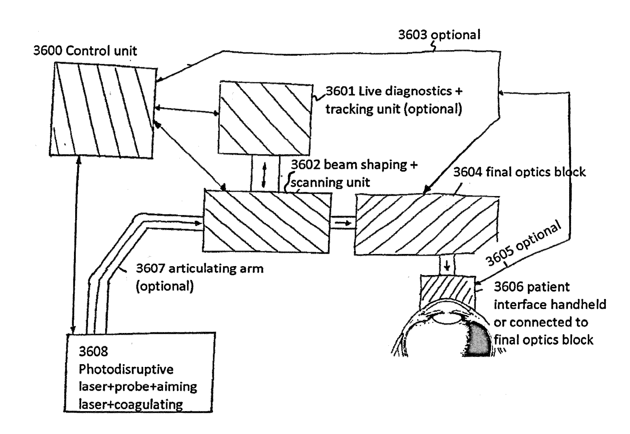
[0078]The word “fs-laser” throughout this disclosure stands for femtosecond laser and is meant to cover any laser source, that can provide pulse durations smaller than 2 for elliptical focus) allows the use of very small pulse energies in the range of <200 micro Joules (preferable range <50 micro joules) while still achieving a photodisruptive (plasma induced optical breakdown) tissue reaction that allows for the creation of a hole (tunnel) in tissue layers in the anterior angle of the eye (e.g the Trabecular Meshwork). FIG. 9 shows the anatomical features of the anterior angle area of the eye. It is critical to keep the pulse energies small since the undesired side effects such as shockwaves and large cavitation bubbles scale with the pulse energy, reduce precision and cause increasing collateral tissue damage around the desired target zone.

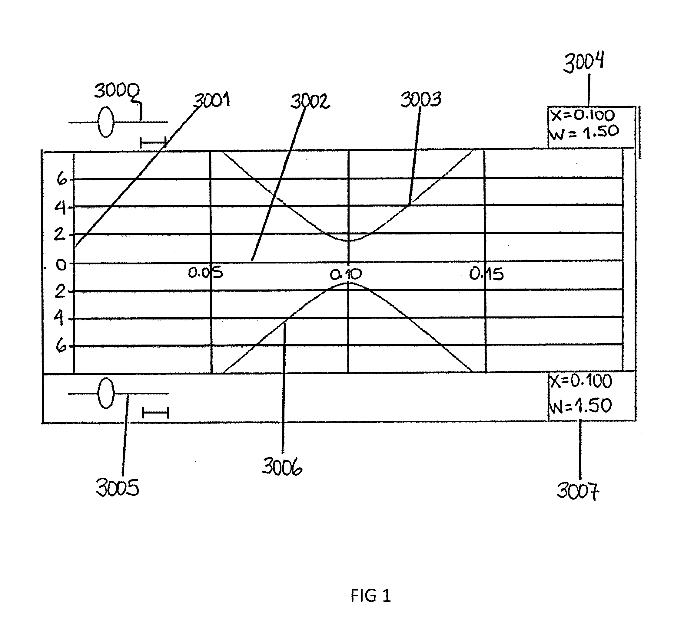
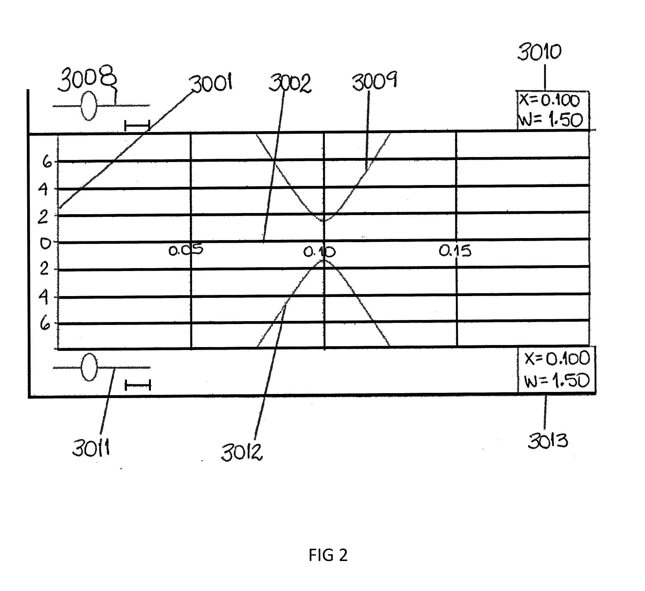
[0079]FIG. 1. The small focus requirement leads to a large focusing beam convergence angle (high numerical aperture NA) in the range of 10-90 d...


PUM


Abstract

The invention relates to systems and methods for accessing tissue layers of the anterior chamber angle of an eye, targeting one or multiple treatment zones within the anterior angle area of the eye and delivering focused photodisruptive laser pulses with pulse durations <50 picoseconds creating channels into various anatomical structures within the anterior angle of the eye.

Description

CROSS-REFERENCE TO RELATED APPLICATIONS[0001]This is a division of application Ser. No. 13 / 442,854 filed on Apr. 10, 2012. This application further claims the benefit of the U.S. provisional application No. 61 / 473,806, filed Apr. 10, 2011, the content of which is considered incorporated by reference herein in its entirety. To the extent the following description is inconsistent with the disclosure of the provisional application, the following description controls.BACKGROUND OF THE INVENTION[0002]Lasers have been used for several decades in the treatment of glaucoma. The 2 most common laser treatments for primary open angle glaucoma (POAG) are ALT (Argon Laser Trabeculoplasty) and SLT (Selective Laser Trabeculoplasty). See for example U.S. Pat. Nos. 3,884,236; 8,066,696; 5,549,596; 6,319,274. They work by applying laser pulses into the Trabecular Meshwork (in the anterior angle of the eye). These laser pulses are focused to around 50 micrometer diameter for ALT and around 400 microme...

Claims


Application Information

Patent Timeline
Patent Type & Authority Applications(United States)
IPC IPC(8): A61F9/008
CPCA61F9/00821A61F2009/00891A61F2009/00868A61F9/00825A61F9/009A61F9/00781
Inventor VERA, VANESSA IHORVATH, CHRISTOPHER
Owner FS EYE
Why Eureka
Try Eureka