Integrated retractor-distractor system for use with modular bone screws

a technology which is applied in the field of retractor and distractors for use with screws, can solve the problems of limiting the range of motion, spinal pathologies, and increasing the likelihood of surgery to correct one or more spinal pathologies

Active Publication Date: 2015-11-05
ORTHOFIX US LLC
View PDF4 Cites 98 Cited by
  • Summary
  • Abstract
  • Description
  • Claims
  • Application Information

AI Technical Summary

Problems solved by technology

With its complex nature, however, there is also an increased likelihood that surgery may be needed to correct one or more spinal pathologies.
Genetic or developmental irregularities, trauma, chronic stress, tumors, and disease can result in spinal pathologies that either limit this range of motion or threaten critical elements of the nervous system housed within the spinal column.

Method used


Image

  • Integrated retractor-distractor system for use with modular bone screws
  • Integrated retractor-distractor system for use with modular bone screws
  • Integrated retractor-distractor system for use with modular bone screws

Examples


Embodiment Construction

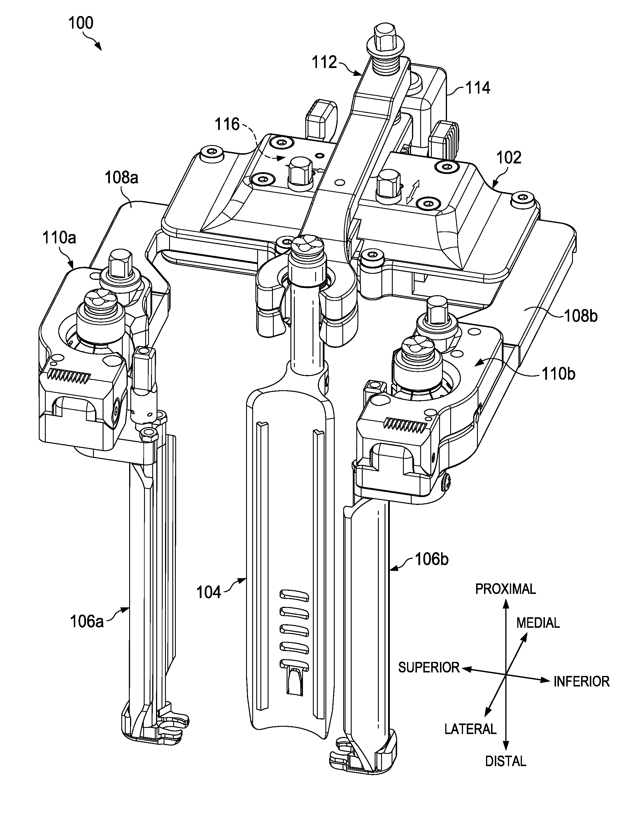
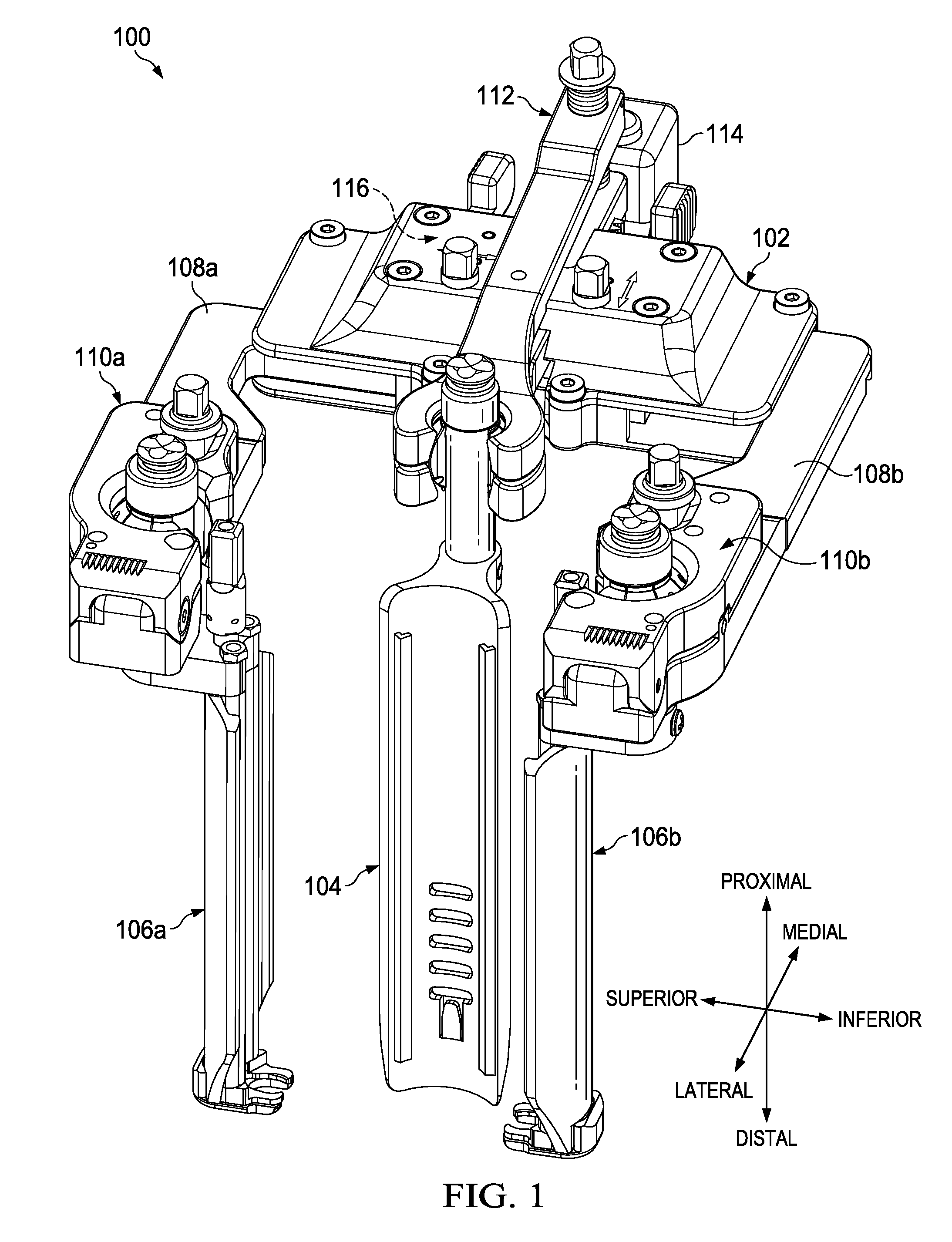
[0030]In the embodiments described below, various components are defined in relation to each other using the positional terms of superior / inferior, medial / lateral, and distal / proximal. In operation and while used during spinal surgery, “superior” refers to closer to the head, while “inferior” refers to closer to the feet. “Medial” refers to closer to the midline (spine) of the body, while “lateral” refers to away from the midline of the body. “Proximal” refers to closer to the user / surgeon, while “distal” refers to away from the user / surgeon. It is to be understood that the superior / inferior designations on various components may be used interchangeably depending on whether the surgeon performs surgery on the spine while standing proximate to the left side of the patient's body or proximate to the right side of the patient's body as long as the superior direction is closer to the patient's head.

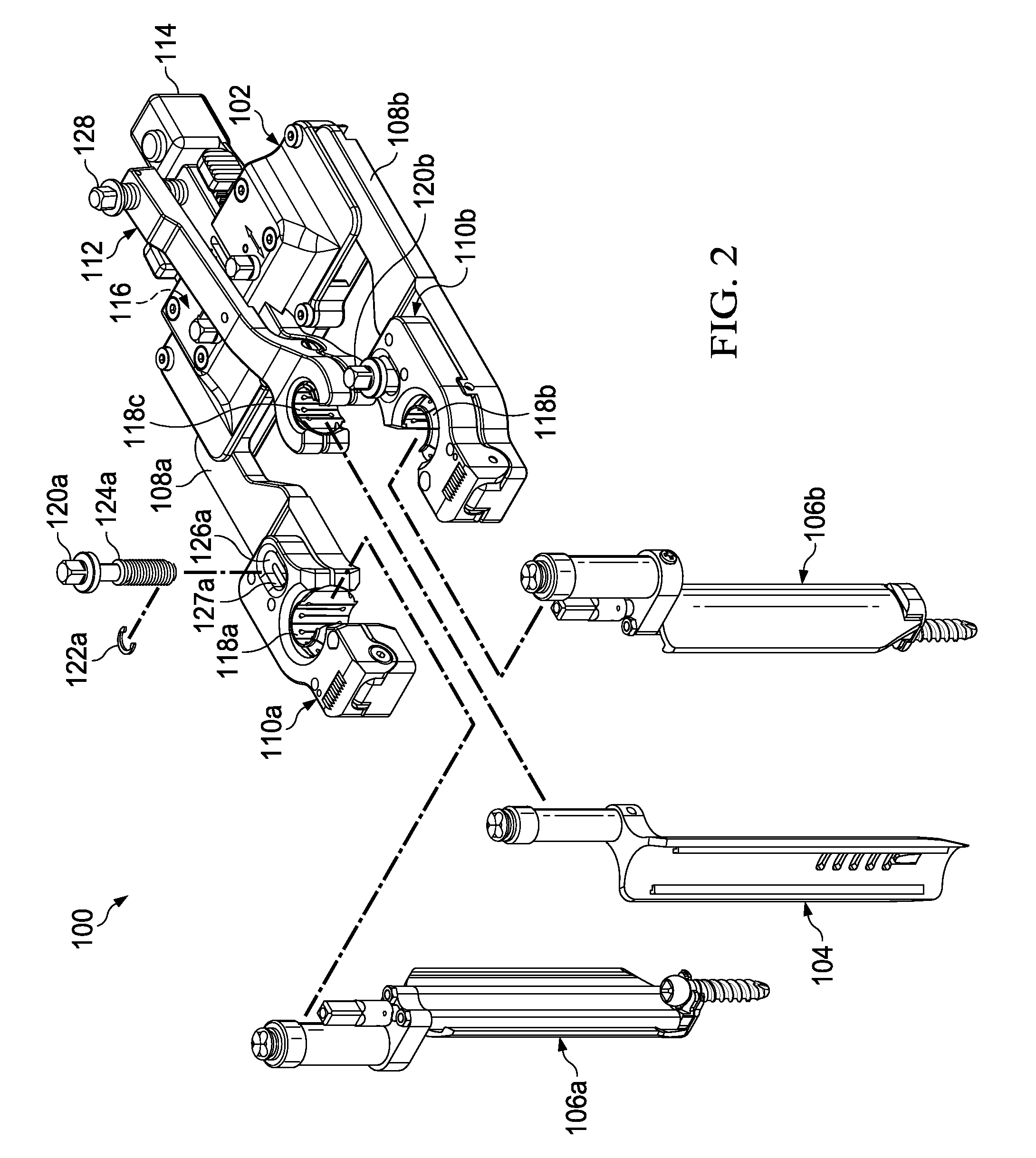
[0031]FIG. 1 depicts a perspective view of an integrated retractor-distractor system 100,...


PUM


Abstract

A retractor-distractor system comprising a frame with slidably coupled superior and inferior arms extending therefrom. The superior arm comprises a superior clamp arm pivotally coupled to a lateral end of the superior arm, a superior ball joint received between the superior clamp arm and the superior arm, and a superior ball joint lock operable to pivot the superior clamp arm proximate to the superior arm, thereby locking the orientation of the superior ball joint. The inferior arm comprises an inferior clamp arm pivotally coupled to a lateral end of the inferior arm, an inferior ball joint received between the inferior clamp arm and the inferior arm, and an inferior ball joint lock operable to pivot the inferior clamp arm proximate to the inferior arm, thereby locking the orientation of the inferior ball joint. The superior and inferior arms are operable to receive a modular blade to retract and distract tissue.

Description

FIELD OF THE INVENTION[0001]The present disclosure relates to retractor and distractor systems for use with screws and more particularly to an integrated retractor-distractor system for use with modular bone screws.BACKGROUND OF THE INVENTION[0002]The spinal column of bones is highly complex anatomical structure that includes over 20 bones coupled to one another, housing and protecting critical elements of the nervous system having innumerable peripheral nerves and circulatory bodies in close proximity. Despite its complexity, the spine is a highly flexible structure, capable of a high degree of curvature and twist in nearly every direction. The more than 20 discrete bones of an adult human spinal column are anatomically categorized as one of four classifications—cervical, thoracic, lumbar, or sacral—and are coupled together sequentially to one another by a tri-joint complex that consists of an anterior disc and two posterior facet joints. The anterior discs of adjacent bones are cu...

Claims


Application Information

Patent Timeline
Patent Type & Authority Applications(United States)
IPC IPC(8): A61B17/02A61F2/46
CPCA61B17/025A61B2017/0256A61F2/4611A61B17/7077A61B17/8891A61B17/0206A61F2/46A61B17/60
Inventor ABIDIN, CIN K.ELMER, BRADQURESHI, SHEERAZASHRAF, NOMAAN
Owner ORTHOFIX US LLC
Why Eureka
Try Eureka