
Automatic prosthesis for above-knee amputees

an amputee and prosthesis technology, applied in the field of orthopaedic appliances, can solve the problems of toe clearance, risk of toes hitting the ground during the swing phase, and the risk of toes hitting the ground during the swing phase, and achieve the effect of restoring the gait ability of amputees

Inactive Publication Date: 2015-11-05
OFFICINE ORTOPEDICHE RIZZOLI SRL
View PDF0 Cites 4 Cited by
  • Summary
  • Abstract
  • Description
  • Claims
  • Application Information

AI Technical Summary

Benefits of technology

The patent is about a new prosthesis for above-knee amputees that helps them walk like normal people. It is designed to replicate the missing limb and can detect the surrounding environment and the person's position. It can also analyze the flexibility and stress-strain of the joints in real-time, which is helpful in adjusting the prosthesis to match the person's needs. Overall, this technology improves the prior art and solution issues of amputees.

Problems solved by technology

One of the many problems of the existing prostheses for above-knee amputees is the risk for the toes to hit the ground during the swing phase, so-called Toe Clearance.
The stiffness of the foot same, does not assist the extension necessary between femur and tibia during the swing phase generating the risk for the toes to hit the ground during the swing phase.
Another problem, during walking on a plane ground in elder patients or in patients that are recovering the gait after above-knee amputation, is realigning the tibia with the femur.
In fact, once passed the TDC between the femoral segment and the tibial segment, a difficulty arises to re-align the femoral segment and the tibial segment owing to a minimum swinging action of the tibial segment.
A further problem is the impossibility, in the existing prostheses, to adjust the pace within a gait cycle.
Yet another problem is the difficulty, for existing prostheses, to adjust the parameters of the gait progressively as the patient gets familiar with the prosthesis.
Further problems are in the range of the prosthesis, which needs of battery motors or electric actuators, where present, as well as in the simplicity of the battery recharge phase.

Method used


Image

  • Automatic prosthesis for above-knee amputees
  • Automatic prosthesis for above-knee amputees
  • Automatic prosthesis for above-knee amputees

Examples


Embodiment Construction

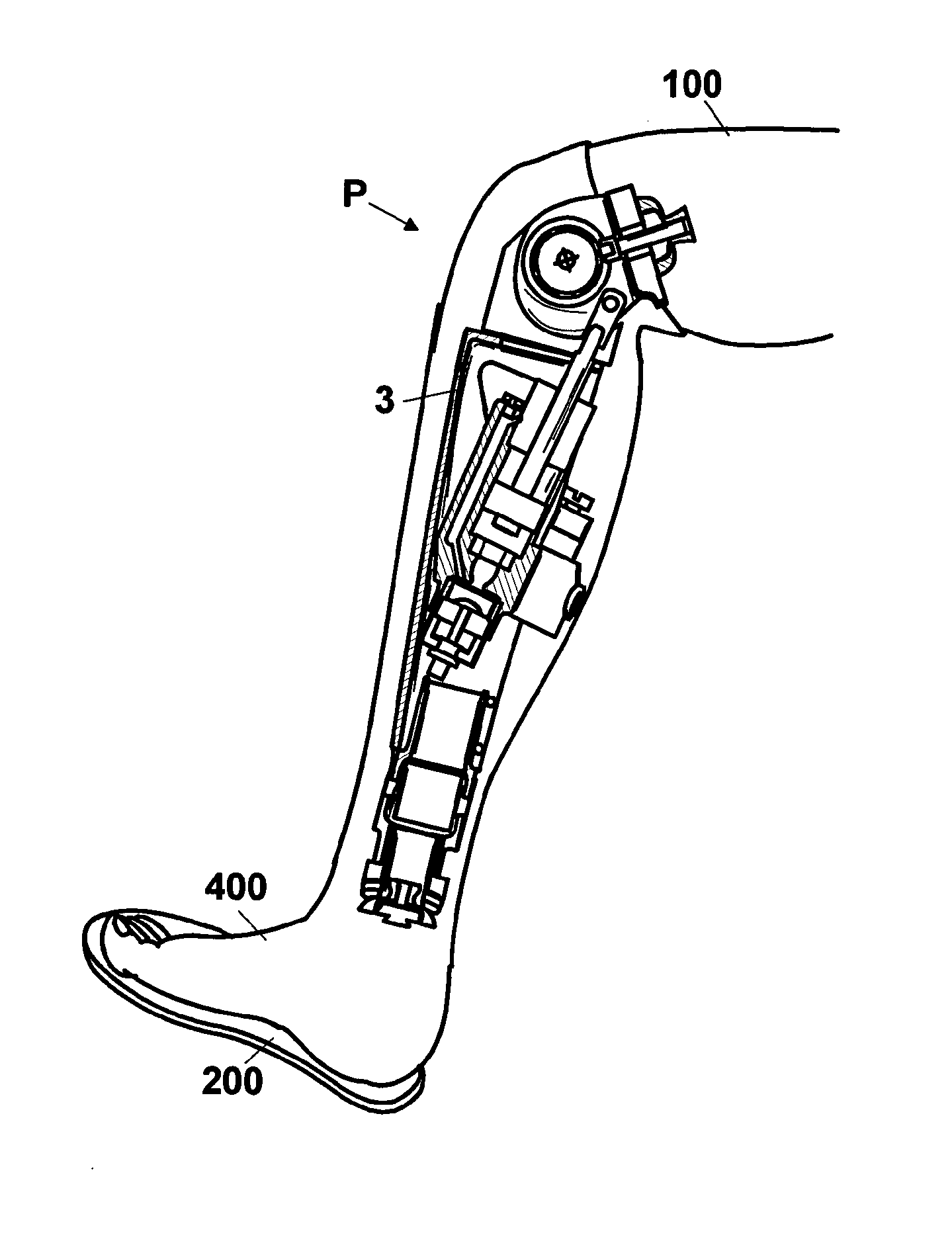
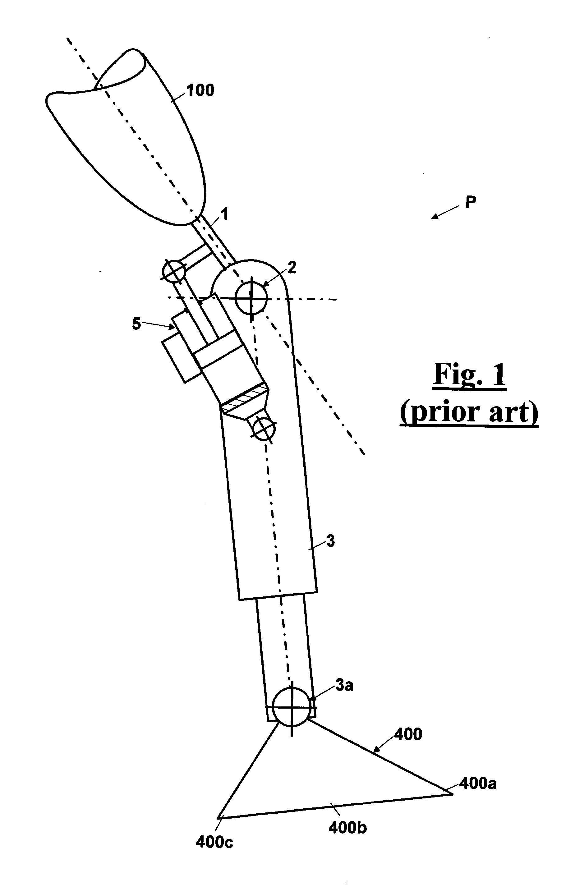
[0168]With reference to FIG. 1, a diagrammatical kinematik view is shown of a prosthesis P of prior art for above-knee amputees, applied to a femoral connection 100 of a possible patient, comprising:[0169]an upper hinge or femoral segment 1 belonging to prosthesis P that accomplishes the connection with the femoral connection 100 of the patient;[0170]an articulation axis 2 that connects femoral segment 1 with a tibial segment 3 and reproduces the movement of a normal knee;[0171]an ankle 3a that connects tibial segment 3 with a prosthetic foot 400;[0172]a damper 5 located between femoral segment 1 and tibial segment 3 that dampens the relative movement between the above described segments and allows the above knee prosthesis P to repeat some of the functions of a normal limb.

[0173]In particular, in the above knee prosthesis P, of FIG. 1, femoral segment 1 and tibial segment 3 are pivotally connected to each other about articulation axis 2 that reproduces the knee movements. Furthermo...


PUM


Abstract

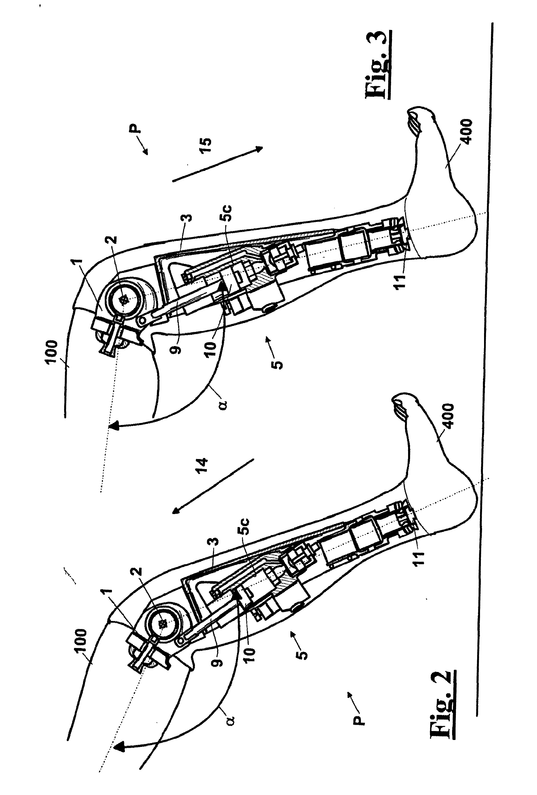
A above knee prosthesis (P) applied to femoral connection (100) of an amputee that comprises a upper hinge (1) connected to femoral connection (100) of the patient, an articulation axis (2) with the function of reproducing the knee movements, a tibia-calf muscle unit (3) pivotally connected to the femoral segment (1) and a damper (5) that reproduces some functions of the calf muscle and ensures to the prosthesis (P) to brake and to allow the sequential swing and stance phases typical of the gait. The damper (5) comprises a cylinder (5c) wherein a piston (10) and a stem (9) act connected to each other and adapted to carry out a damping reaction of said damper responsive to the forces loaded on the prosthesis. In particular, a force transducer is provided in the damper (5) arranged, in particular, in the stem (9) with a microprocessor that receives a force signal from the transducer and operates means for adjusting the reaction of the damper responsive to the detected force signal. Exemplary embodiments are equipped with means for adjusting the gait parameters during a gait cycle, means for exploiting the energy dissipated by the prosthesis, means to assist the charge and the change of batteries, means to know the direction and / or the intensity of resultant forces transmitted through the prosthesis.

Description

FIELD OF THE INVENTION [0001]The present invention relates to the field of orthopaedic appliances and more precisely it relates to an automatic prosthesis for above-knee amputees.[0002]Furthermore, the invention relates to an electronic apparatus capable to control this prosthesis.DESCRIPTION OF THE TECHNICAL PROBLEM [0003]Various types are known of prostheses for above-knee amputees. In many of these types a configuration is provided with a femoral segment and a tibial segment pivotally connected to each other about an articulation axis that reproduces the knee movements. Furthermore, a hydraulic damper is provided that connects the femoral segment with the tibial segment. An example of these prostheses is disclosed in JP52047638, GB826314, U.S. Pat. No. 4,212,087, U.S. Pat. No. 3,599,245.[0004]The tibial segment is articulated by an ankle to a foot having toes, a sole of the foot and a heel, and the knee movements can be divided into a phase so-called swing, between bringing the t...

Claims


Application Information

Patent Timeline
Patent Type & Authority Applications(United States)
IPC IPC(8): A61F2/60
CPCA61F2/60A61F2002/607A61F2002/701A61F2/72A61F2002/608A61F2/6607A61F2/70A61F2002/5006A61F2002/5033A61F2002/6621A61F2002/6642A61F2002/665A61F2002/6818A61F2002/6836A61F2002/702A61F2002/704A61F2002/7625A61F2002/7635A61F2002/764A61F2002/768A61F2/74A61F2/748
Inventor BALBONI, ALESSANDROBALLI, LEONARDODE MICHELI, DENIS MATTIADONATI, GABRIELEFERRINI, NICOLA
Owner OFFICINE ORTOPEDICHE RIZZOLI SRL
Learn More