Frame hanging wire post with locking connector

a technology of locking connector and hanging wire, which is applied in the direction of machine supports, other domestic objects, mechanical apparatus, etc., can solve the problems of stiff stranded wires that do not lend themselves, the eyelet is relatively weak, and is subject to bending and/or dislodging from the picture frame, etc., to facilitate connecting and adjusting lengths, facilitate threading, and facilitate the effect of attachment to the fram

Inactive Publication Date: 2015-11-19
MILLER ROBERT W
View PDF2 Cites 1 Cited by
  • Summary
  • Abstract
  • Description
  • Claims
  • Application Information

AI Technical Summary

Benefits of technology

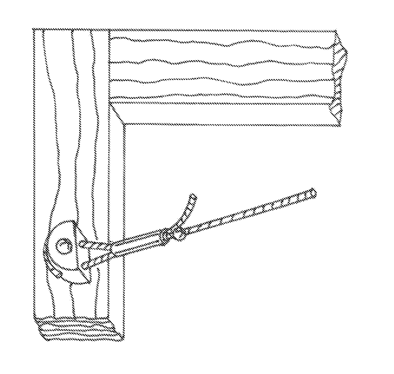
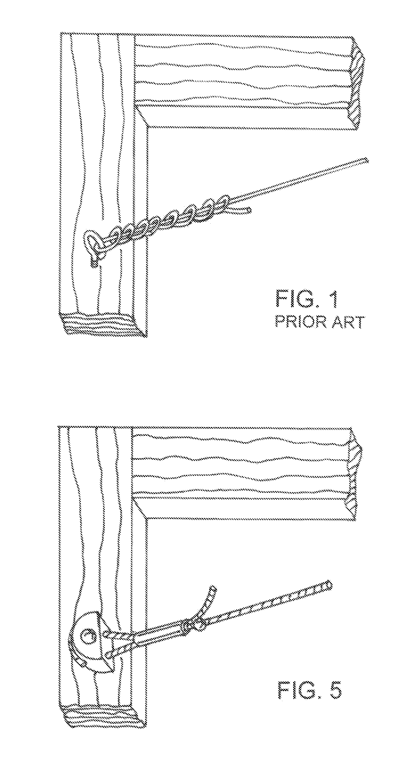
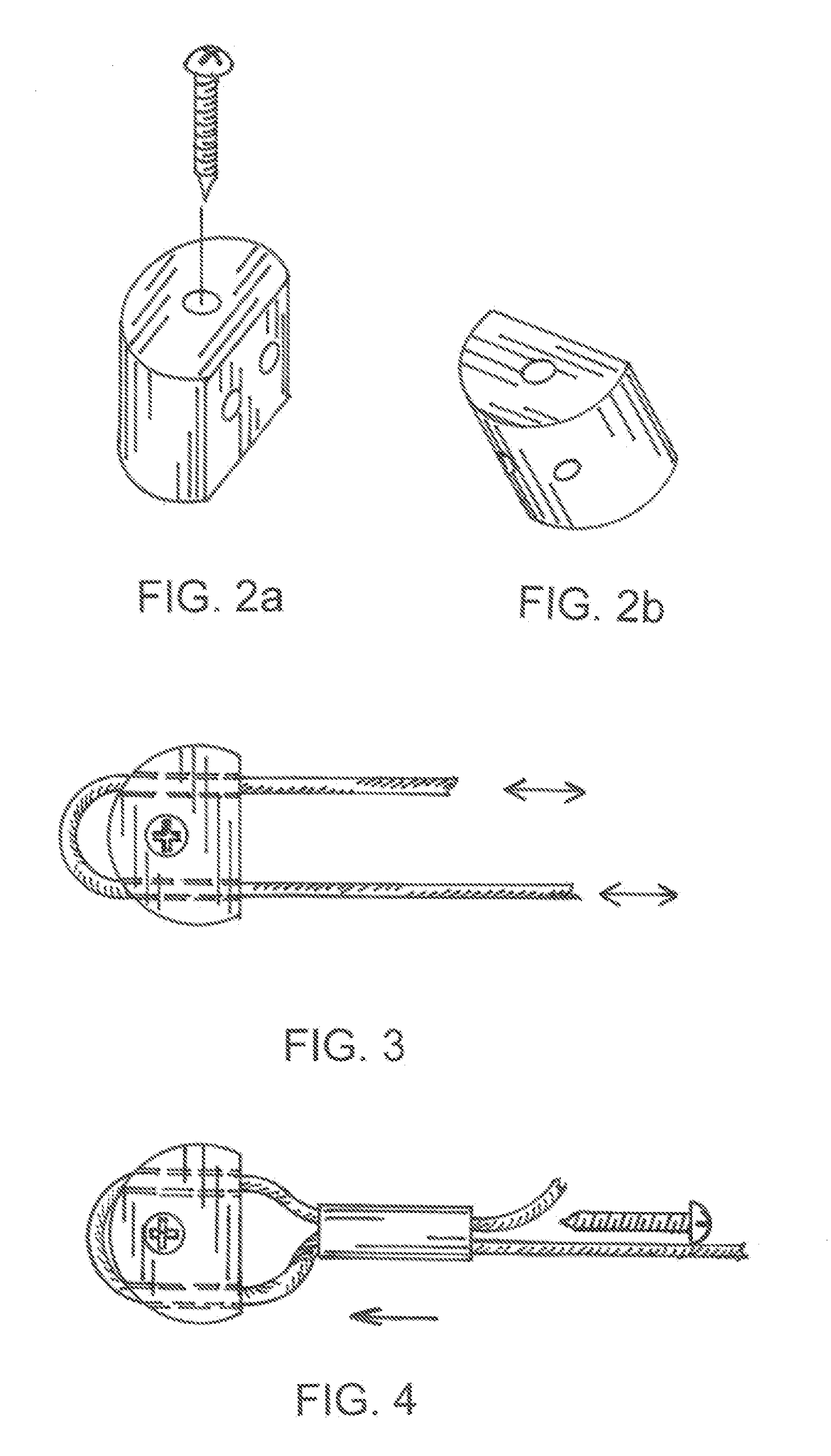
[0004]Accordingly, it is the general purpose of the present invention to provide a hitching post for frames of decorative hanging items that will facilitate connecting and adjusting lengths of the structural hanging wires. The hitching post described in the drawings, can be easily attached to frame, and then be quickly threaded with the hanging wire. The hanging wire is adjusted to desired length and then locked into position with the described parallel line connector. This preferred parallel line connector type is an improvement over the typical swaged ferrule type of parallel line splice connector. This preferred parallel line connector has a very low profile, is easily installed with no special tooling and develops a connected strength equal to the rated load for the structural wire. All current parallel line wire connectors require that with coated wire, the coating must be removed in order to install connector. With this inventive connector, the thread of the advancing locking screw will slice through the polymer coating on coated hanging wires to provide a mechanical lock on the steel strands of the wire, thus enabling the connector to be used with coated wire. This inventive frame post with connector will provide an assembly strength of wire to frame equal to the load rating of the hanging wire.

Problems solved by technology

The eyelet is relatively weak and is subject to bending and / or dislodging from picture frame.
Obtaining the exact desired length of a hanging wire while tying in a knot is the first part of problem, and the second is the stiff stranded wires do not lend themselves to be formed into taut configurations of a knot.

Method used


Image

  • Frame hanging wire post with locking connector
  • Frame hanging wire post with locking connector
  • Frame hanging wire post with locking connector

Examples


Embodiment Construction

[0011]This basic hitching post is a short length (.60″ typ) of a circular / semicircular rod section with a center point bore (.160″ ID typical) that will accept the attach screw to attach this post section to frame. This post section will typically have parallel bore holes that allow the hanging wire to be threaded through, looped around back side of circular section of post, and threaded back through second bore hole with enough extra length to allow for installation of the parallel line splice connector. Ideally the component materials for completing an installation would be supplied as a kit; containing the particular strength-rated hanging wire and the corresponding hitch posts with locking connectors. The bore hole diameters for posts would typically be about 1.2 times the actual wire OD. The centerline spacing between the parallel boreholes would be about 4.2 times the wire OD. Typically the diameter of post would be .50 inch for wire up to .050″OD, and .75 inch for wires up to...


PUM


Abstract

A hanging wire post with a locking connector for decorative hanging applications. This hanging wire post would be alternate to using eyelets or D-rings for attachment point of hanging wire to frame. This hanging post will install to frame with a single center-point screw. This post supports the hanging wire which is threaded through and around backside of post resulting in a frictional grip on wire that facilitates wire length adjustment. The hanging wire is then locked into position with the parallel line locking connector. The result is a very high strength end connection, and very quick and precise installation. No frustration of trying to tie precise knots in stranded wire or stranded wire rope. This device will work equally well with coated or uncoated stranded wire and wire rope.

Description

CROSS-REFERENCE TO RELATED APPLICATIONS[0001]This application is related to U.S. patent application Ser. No. 13 / 495,638 filed Jun. 13, 2012 and is incorporated herein by reference.BACKGROUND OF THE INVENTION[0002]Hanging wires for picture frames and other architectural items are typically suspended with stranded load-rated steel wire with wire OD's of .032 to .092″. The stranded wires are now available with a polymeric coating which prevents the sheared ends of wire from having splayed strands that can easily puncture skin.[0003]Decorative hangings are typically supported in a structural frame which will be supported by a hanging wire that attaches to either eyelets or D-rings attached to frame. The eyelet is relatively weak and is subject to bending and / or dislodging from picture frame. The D-ring having a heavier attach screw(s) is a better method for attaching to frame. However both types will require tying the wire to the eyelet or D-ring. Obtaining the exact desired length of a...

Claims


Application Information

Patent Timeline
Patent Type & Authority Applications(United States)
IPC IPC(8): A47G1/16F16G11/14F16G11/05
CPCA47G1/1666F16G11/14F16G11/05F16G11/146
Inventor MILLER, ROBERT W.
Owner MILLER ROBERT W
Why Eureka
Try Eureka