Illuminating Device and Vehicle Lamp Comprising Same
a technology of illumination device and vehicle lamp, which is applied in the direction of point-like light source, transportation and packaging, lighting and heating apparatus, etc., can solve the problems of difficult adjustment of light distribution in implementing illumination, limit in applying surface light source as illumination, etc., and achieve excellent light concentration function and stable light concentration function. , the effect of excellent light concentration function
- Summary
- Abstract
- Description
- Claims
- Application Information
AI Technical Summary
Benefits of technology
Problems solved by technology
Method used
Image
Examples
first exemplary embodiment
1. FIRST EXEMPLARY EMBODIMENT
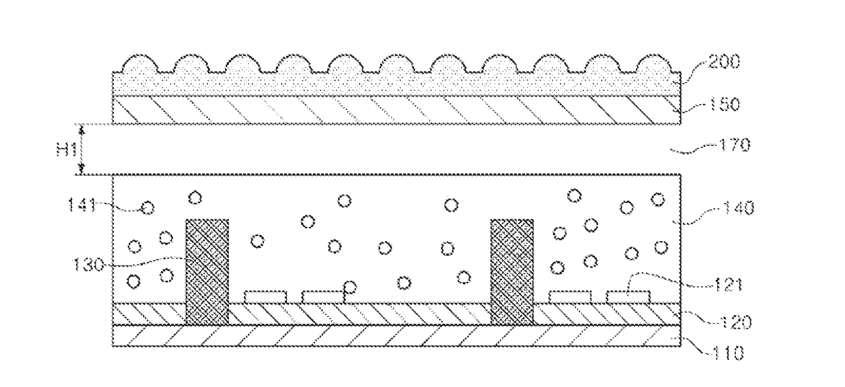
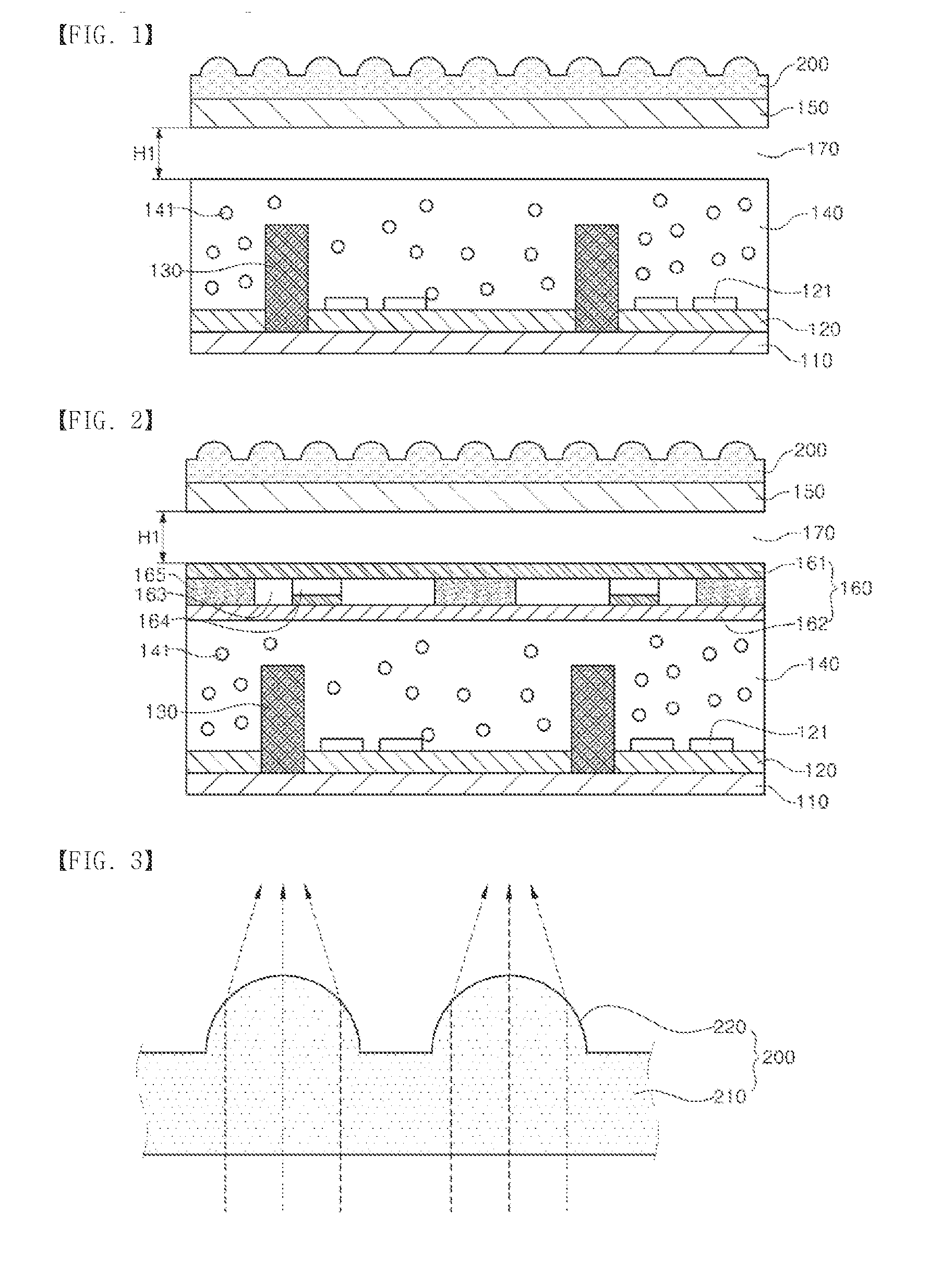
[0036]FIGS. 1 and 2 are cross-sectional and conceptual views illustrating a main part of an illuminating device according to a first exemplary embodiment of the present invention.
[0037]Referring to FIGS. 1 and 2, an illuminating device according to a first embodiment of the present invention may include: a surface light emitting module 100 including a light guide member 140 intended for burying a light source 130: and a condensing member 200 on the surface light emitting module 100. In the present exemplary embodiment of the present invention, the condensing member 200 is disposed on the surface light emitting module 100 so that an effect for condensing light emitted from the surface light emitting module 100 can be maximized. That is, as the condensing member capable of condensing the light emitted from the surface light emitting module is provided, a the distribution of light property of the surface light source is adjusted so that a legal standard can...
second exemplary embodiment
2. SECOND EXEMPLARY EMBODIMENT
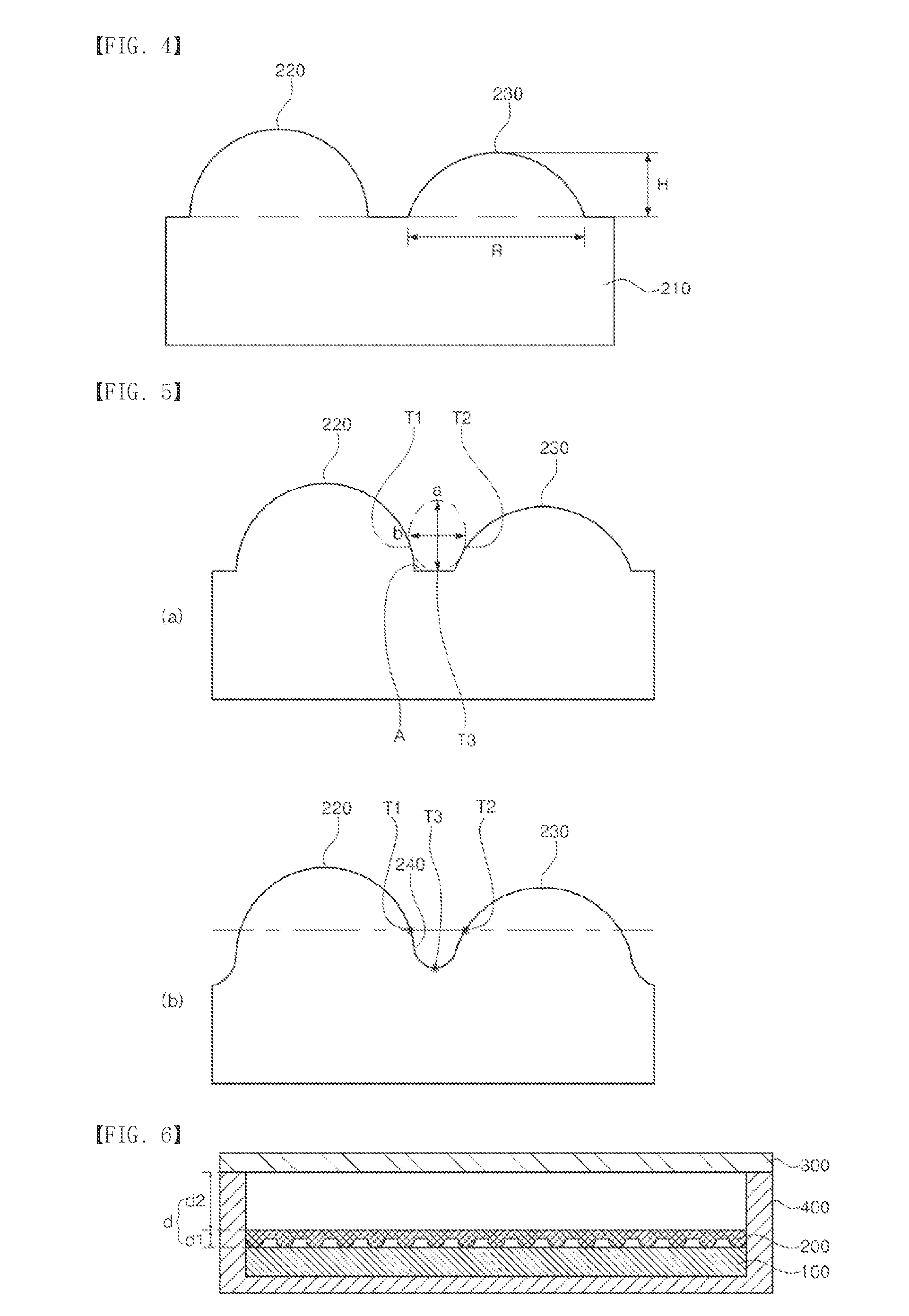
[0065]FIG. 6 is a conceptual view illustrating a structure of the second exemplary embodiment further including a light shielding module 400 in which the surface light emitting module and the condensing member described in the first exemplary embodiment are accommodated.
[0066]According to the second exemplary embodiment, the illuminating device may include the surface light emitting module 100 and the condensing member 200 of the first exemplary embodiment of the present invention, and in particular, the illuminating device may further include the light shielding module 400 in which the surface light emitting nodule 100 and the condensing member 200 are accommodated. In such a case, a second diffusion member 300 intended for diffusing condensed light may be disposed on an upper surface of the condensing member 200. The surface light emitting module 100 and the condensing member 200 may be mounted to be accommodated in the light shielding module 400 havi...
third exemplary embodiment
3. THIRD EXEMPLARY EMBODIMENT
[0073]FIG. 8 is a cross-sectional and conceptual view of a main part illustrated for explaining the structure of a third exemplary embodiment of the present invention.
[0074]The third exemplary embodiment results from modifying the structure of the condensing member from the structure of the second exemplary embodiment The same reference numeral of the condensing member is used to designate the same element.
[0075]The third exemplary embodiment results from changing the structure of the condensing member in the structure of the second exemplary embodiment. The reference numeral of the condensing member corresponding to the same element
[0076]Referring to FIG. 8, an illuminating device according to the third exemplary embodiment of the present invention includes: a surface light emitting module 100 including a light guide member disposed to bury a plurality of light sources: and a condensing member 500 having perforated optical patterns intended for condensi...
PUM
 Abstract
Description
Claims
Application Information
 - R&D
- Intellectual Property
- Life Sciences
- Materials
- Tech Scout
- Unparalleled Data Quality
- Higher Quality Content
- 60% Fewer Hallucinations
Browse by: Latest US Patents, China's latest patents, Technical Efficacy Thesaurus, Application Domain, Technology Topic, Popular Technical Reports.
© 2025 PatSnap. All rights reserved.Legal|Privacy policy|Modern Slavery Act Transparency Statement|Sitemap|About US| Contact US: help@patsnap.com


