Position detector, and lens apparatus and image pickup apparatus including the position detector

Active Publication Date: 2016-01-07
CANON KK
View PDF3 Cites 3 Cited by
  • Summary
  • Abstract
  • Description
  • Claims
  • Application Information

AI Technical Summary

Benefits of technology

The present invention provides a position detector that can detect scratches or dust on the surface of a lens or image pickup apparatus. This allows for better maintenance and repair of the apparatus.

Problems solved by technology

The technology disclosed in Japanese Patent Application Laid-Open No. 2002-39727 can be adapted only to an encoder configured to obtain the absolute position by reading the pattern array, and is not applicable to an incremental type encoder or an encoder configured to obtain the absolute position based on a Vernier type.
In the technology disclosed in Japanese Patent Application Laid-Open No. 2011-247879, in a case of a scratch or dust having the same size as a width of a cycle, an effect of the scratch or dust is exerted on the respective periodic signals to the same degree, which leads to a problem in that an error cannot be detected even by conducting the comparison.

Method used


Image

  • Position detector, and lens apparatus and image pickup apparatus including the position detector
  • Position detector, and lens apparatus and image pickup apparatus including the position detector
  • Position detector, and lens apparatus and image pickup apparatus including the position detector

Examples


first embodiment

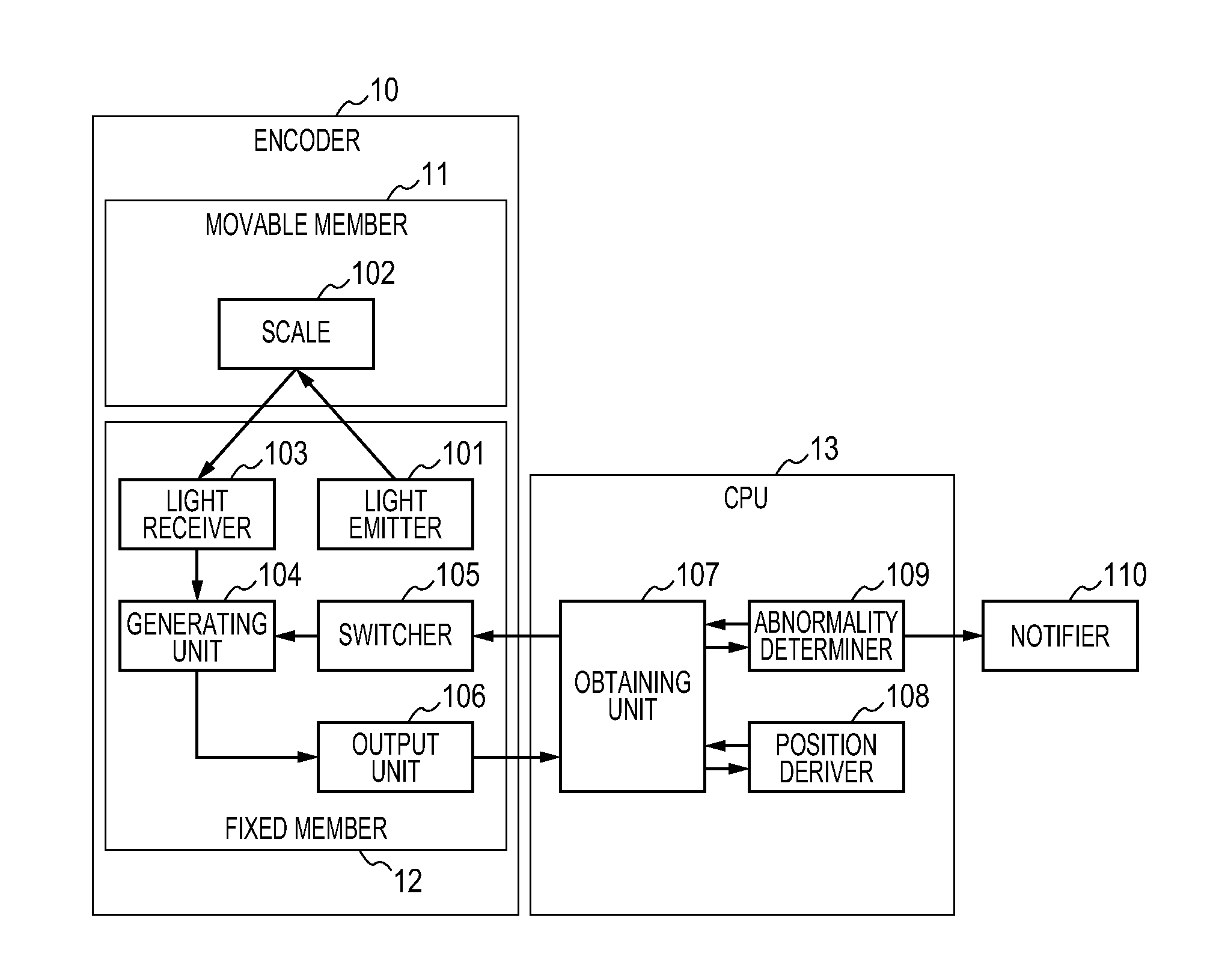
[0041]In the following, a position detector according to a first embodiment of the present invention is described with reference to FIG. 1 to FIG. 9D.

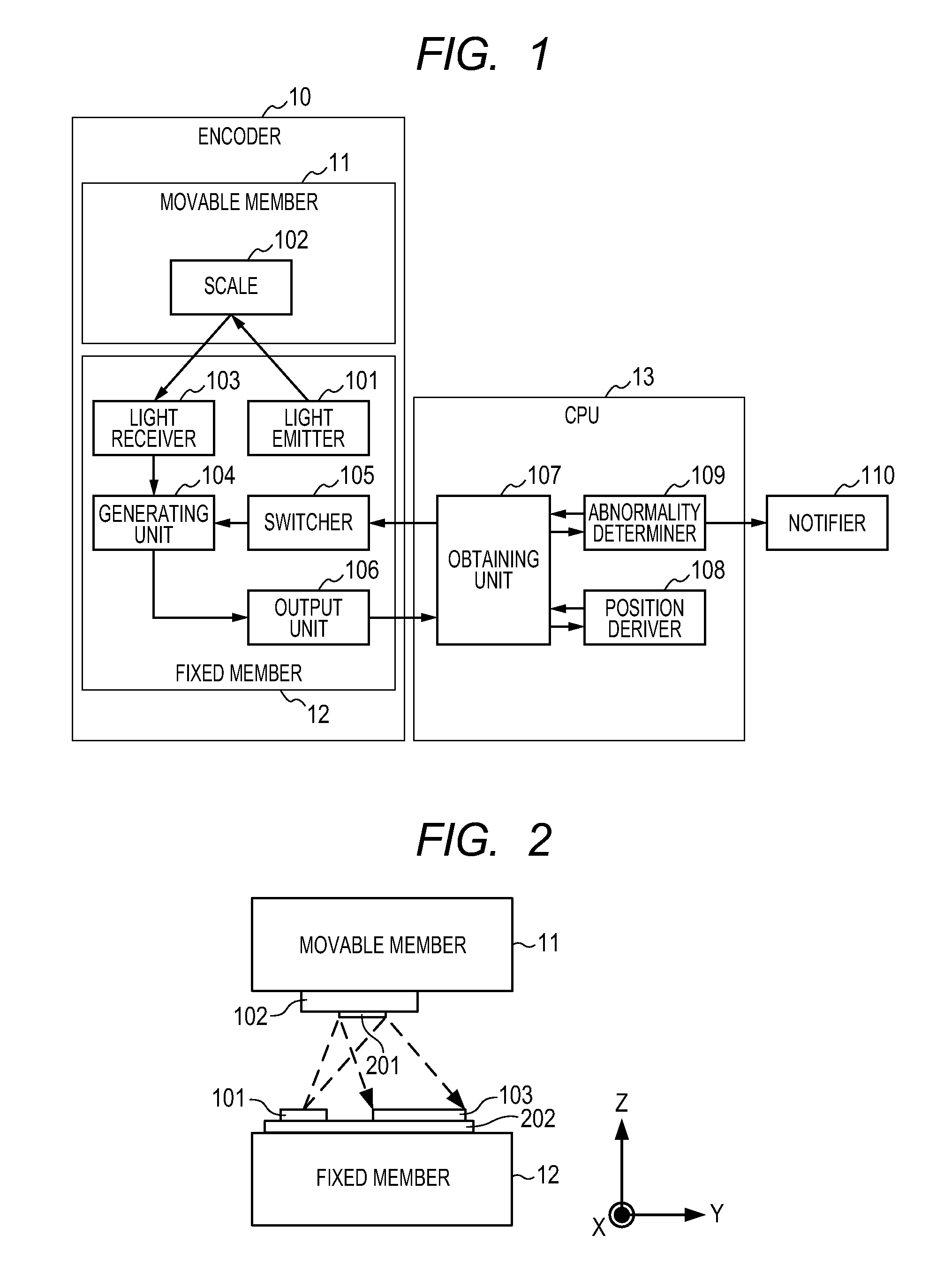
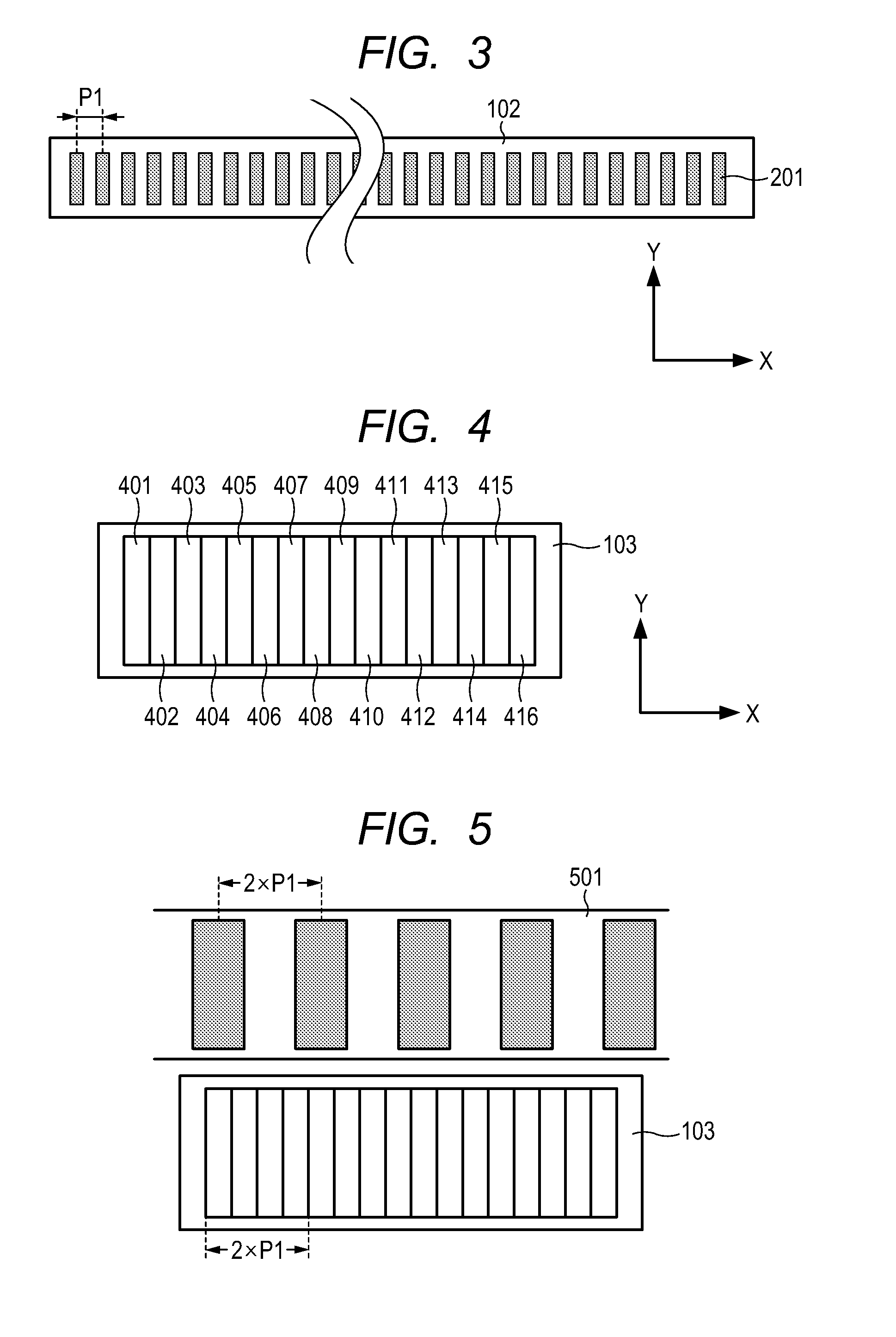
[0042]FIG. 1 is a configuration block diagram of the position detector according to the first embodiment of the present invention. In FIG. 1, a light emitter 101 is a light source formed of an LED or the like, and emits light to a scale 102. The scale 102 reflects the light emitted from the light emitter 101 toward a light receiver 103. In this embodiment, the light emitter 101 and the light receiver 103 construct a detector. The light receiver 103 is an optical sensor configured to convert the light reflected by the scale 102 into an electric signal. Note that, the scale 102 and the light receiver 103 are described later in detail.

[0043]A generating unit 104 is a generating unit configured to selectively generate, from signals received from the light receiver 103, a periodic signal corresponding to a position of a movable member or an...

second embodiment

[0089]In the following, a position detector according to a second embodiment of the present invention is described with reference to FIG. 10 to FIG. 17.

[0090]FIG. 10 is a configuration block diagram of the position detector according to the second embodiment of the present invention. The same components as those of FIG. 1 serving as the configuration block diagram according to the first embodiment are denoted by the same reference numerals, and hence descriptions thereof are omitted.

[0091]A scale 1002 has a track pattern that is different from that of the first embodiment and is obtained by multiplexing two kinds of track patterns. The details thereof are described later.

[0092]A generating unit 1004 is a signal generating unit configured to generate the abnormality detection signal and two kinds of periodic signals that are generated from two kinds of track patterns multiplexed in the scale 1002 and that correspond to the respective track patterns.

[0093]A switcher 1005 is a switcher...


PUM


Abstract

A position detector, including: a scale including a pattern array formed cyclically in a movement direction, the scale being provided to a fixed member or a movable member; a detector including detection elements arranged in the movement direction, the detector being provided to the other; a generating unit that selectively generates, from signals received from the detection elements, a first signal obtained by a first combination of the signals or a second signal obtained by a second combination of the signals; an output unit that outputs the first or second signal received from the generating unit; and a switcher that switches over between the first and second signals as a signal to be generated, wherein the first signal changes within a first range, corresponding to a relative position; and the second signal does not change beyond a second range smaller than the first range, corresponding to the relative position.

Description

BACKGROUND OF THE INVENTION[0001]1. Field of the Invention[0002]The present invention relates to a position detector, and more particularly, to an absolute position detector configured to detect an absolute position, and a lens apparatus and image pickup apparatus including the absolute position detector.[0003]2. Description of the Related Art[0004]Hitherto, there is known a technology for detecting an abnormality such as a scratch or dust in a position detector for measuring a moving distance of an object.[0005]In Japanese Patent Application Laid-Open No. 2002-39727, there is disclosed a technology of a position detector configured to obtain an absolute position by reading a pattern array, the position detector including a sensor that covers an area larger than a pattern reading area, in which a correct position is obtained by shifting an area to be read back and forth so as to read the area when an abnormality occurs in a pattern.[0006]Further, in Japanese Patent Application Laid-...

Claims


Application Information

Patent Timeline
IPC IPC(8): G01D5/347
CPCG01D5/34715G01D5/34776G01D3/08G01D5/24466G01D5/34746
Inventor YONEZAWA, TAKESHI
Owner CANON KK
Why Eureka
Try Eureka