Driver circuit for switching element

a technology of switching element and driver circuit, which is applied in the direction of pulse generator, pulse technique, instruments, etc., can solve the problems of the inability to detect the open circuit state between the control terminal and the driver circuit, and the inability to detect the state in which the connection line is not connected to the control terminal

Active Publication Date: 2015-01-22
DENSO CORP
View PDF1 Cites 0 Cited by
  • Summary
  • Abstract
  • Description
  • Claims
  • Application Information

AI Technical Summary

Benefits of technology

[0009]It is thus desired to provide a driver circuit for a switching element that is capable of detecting an open circuit state between a control terminal of a voltage-controlled switching element and a driver circuit.
[0010]An exemplary embodiment provides a driver circuit for a switching element that is connected to a control terminal of a voltage-controlled switching element via a connection line and drives the switching element. The driver circuit for a switching element includes: charging means, discharging means, voltage detecting means and open circuit detecting means. The charging means switches the element to an ON state by charging the control terminal of the switching element via the connection line. The discharging means switches the switching element to an OFF state by discharging the control terminal of the switching element via the connection line. The voltage detecting means detects the voltage at a predetermined position on the connection line. The open circuit detecting means detects an open circuit state between the control terminal and the predetermined position based on the speed of change in the voltage at the predetermined position detected by the voltage detecting means when the switching element is switched to the ON state or the OFF state.
[0011]In the present disclosure, the voltage-controlled switching element is switched to the ON state when the control terminal of the switching element is charged with electrical charge from the driver circuit via the connection line. In addition, the switching element is switched to the OFF state when electrical charge is discharged from the control terminal of the switching element to the driver circuit via the connection line. The voltage at a predetermined position on the connection line is detected when the switching element is switched to the ON state or the OFF state. An open circuit state between the control terminal of the switching element and the predetermined position on the connection line is detected based on the speed of change in the detected voltage.
[0012]When the control terminal and the connection line are connected normally, the voltage at the predetermined position on the connection line is the same as the voltage applied to the control terminal from the driver circuit via the connection line. On the other hand, even when the connection between the control terminal and the predetermined position on the connection line is in an open circuit state, the voltage at the predetermined position is the same as the voltage applied to the control terminal when the connection is normal.
[0013]However, the inventors of the present disclosure have discovered that the speed of change in the voltage at the predetermined position when the switching element is switched to the ON state or the OFF state differs between normal connection and when the connection between the control terminal and the predetermined position on the connection line is in the open circuit state. Specifically, the inventors of the present disclosure have discovered that, as a result of the capacitance present between the control terminal and another terminal of the switching element, the voltage at the predetermined position increases or decreases more gradually when the connection is normal, compared to when the connection between the control terminal and the predetermined position is in an open circuit state.
[0014]Therefore, the open circuit state between the control terminal and the predetermined position on the connection line can be detected based on the speed of change in the voltage at the predetermined position when the switching element is switched to the ON state or the OFF state. In other words, the open circuit state between the control terminal of the switching element and the driver circuit can be detected.

Problems solved by technology

However, even when the detection circuit described in JP-A-2008-249642 is applied, the open circuit state between the control terminal and the potential detection position on the connection line cannot be detected.
In particular, a state in which the connection line is not connected to the control terminal cannot be detected.
Therefore, a problem occurs in that, unless the current is sent to the switching element, the open circuit state between the control terminal and the driver circuit cannot be detected.

Method used


Image

  • Driver circuit for switching element
  • Driver circuit for switching element
  • Driver circuit for switching element

Examples


Embodiment Construction

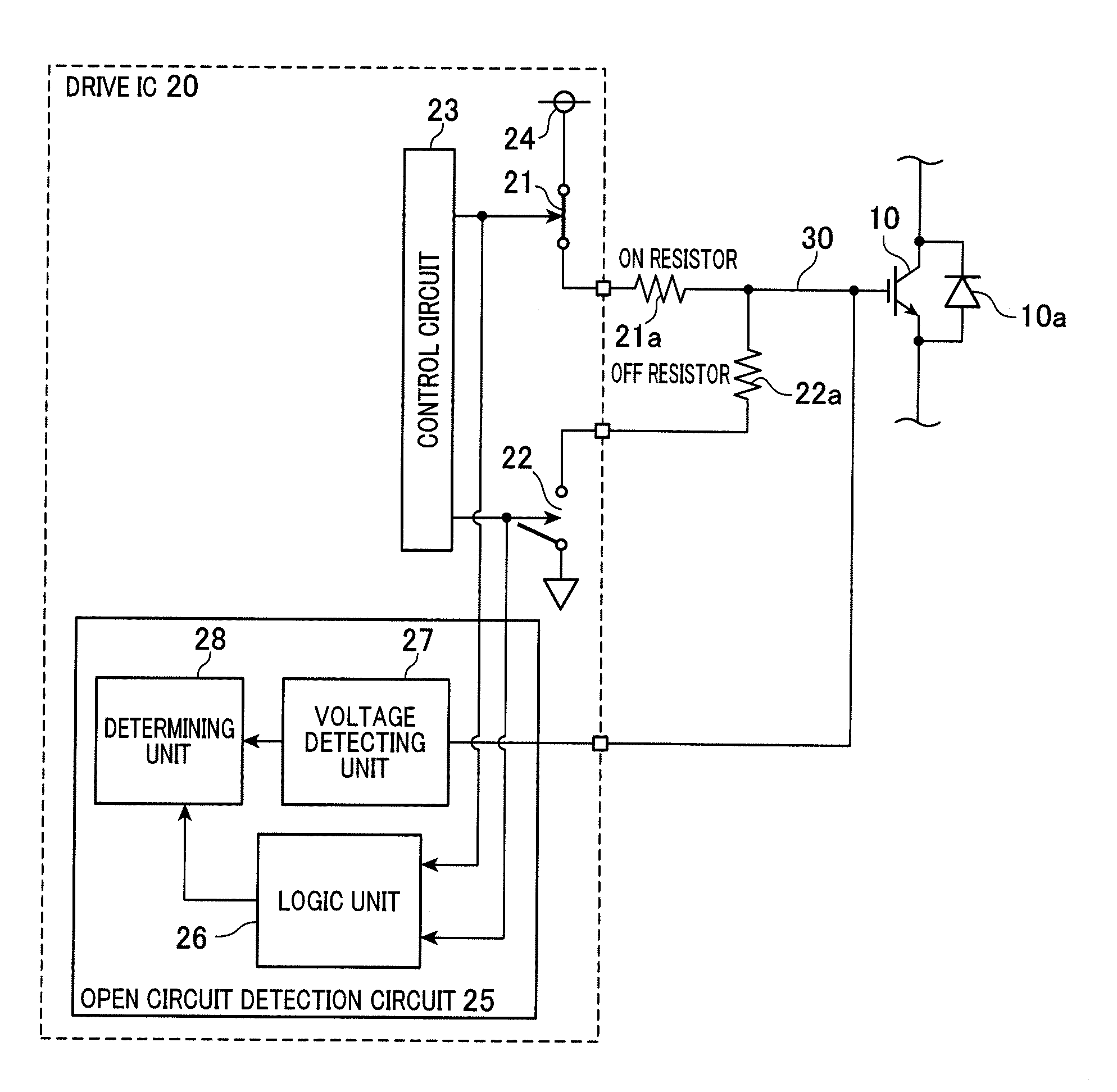
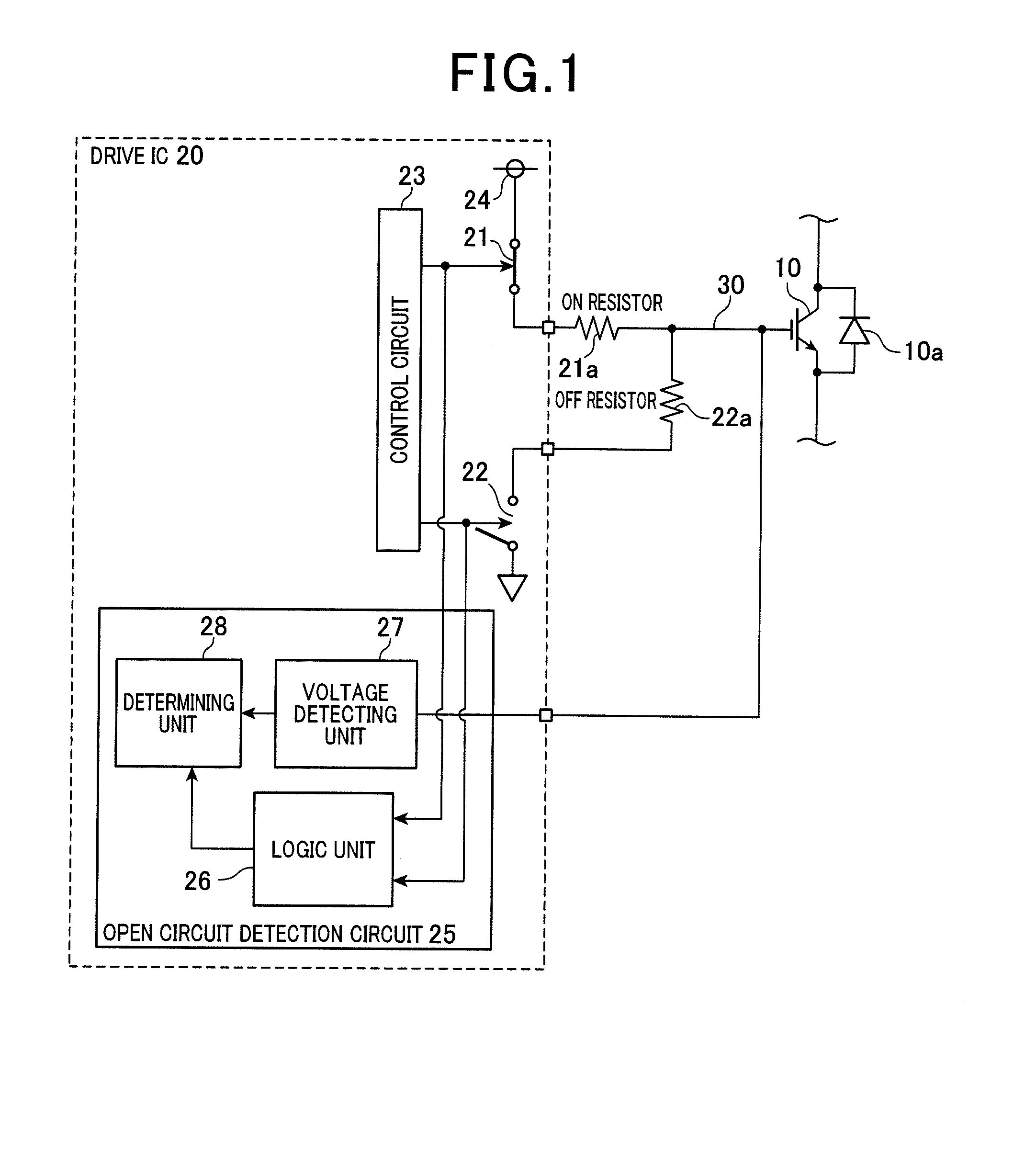
[0018]An embodiment of a driver circuit for a switching element used to drive an insulated-gate bipolar transistor (IGBT) will hereinafter be described with reference to the drawings.

[0019]First, an electrical configuration including a drive integrated circuit (IC) 20 (driver circuit for a switching element) according to the present embodiment will be described with reference to FIG. 1. The drive IC 20 includes an ON-drive switching element 21, an OFF-drive switching element 22, a control circuit 23, a drive power source 24, and an open circuit detection circuit 25. The drive IC 20 is connected to a gate terminal (control terminal) of an IGBT 10 (switching element) by a connection line 30. A charging means is configured by the ON-drive switching element 21, the control circuit 23, and the drive power source 24. A discharging means is configured by the OFF-drive switching element 22 and the control circuit 23.

[0020]The IGBT 10 is a voltage-controlled switching element that is driven ...


PUM


Abstract

A driver circuit is connected to a control terminal of a voltage-controlled switching element via a connection line. The drive circuit drives the switching element. The switching element is switched to an ON state by charging the control terminal of the switching element via the connection line. The switching element is switched to an OFF state by discharging the control terminal of the switching element via the connection line. A voltage at a predetermined position on the connection line is detected. An open circuit state between the control terminal and the predetermined position is detected based on a speed of change in the detected voltage at the predetermined position when the switching element is switched to the ON state or the OFF state.

Description

CROSS-REFERENCE TO RELATED APPLICATION[0001]This application is based on and claims the benefit of priority from Japanese Patent Application No. 2013-147320, filed Jul. 16, 2013, the disclosure of which is incorporated herein in its entirety by reference.BACKGROUND[0002]1. Technical Field[0003]The present invention relates to a driver circuit for a voltage-controlled switching element.[0004]2. Related Art[0005]JP-A-2008-249642 discloses a detection circuit having an electrical configuration that includes a potential supply unit, an internal circuit, and a supply path. The potential supply unit outputs a predetermined potential obtained by a potential of an external power source and ground potential being divided by a resistor element. The internal circuit is an integrated circuit or the like. The supply path connects the potential supply unit and the internal circuit. In this electrical configuration, the detection circuit detects an open circuit state between the potential supplyin...

Claims


Application Information

Patent Timeline
Patent Type & Authority Applications(United States)
IPC IPC(8): H03K17/00
CPCH03K17/00H03K17/18G01R31/026G01R31/3277G01R31/52G01R31/54
Inventor WATANABE, KEISUKE
Owner DENSO CORP
Why Eureka
Try Eureka