Unsteadiness detection device, unsteadiness detection system and unsteadiness detection method

Active Publication Date: 2020-08-20
MITSUBISHI ELECTRIC CORP
View PDF0 Cites 0 Cited by
  • Summary
  • Abstract
  • Description
  • Claims
  • Application Information

AI Technical Summary

Benefits of technology

The invention is a device that can detect the operation of facilities that use binary digital signals. It is designed with a specific configuration, making it able to detect the status of these facilities.

Problems solved by technology

However, as facilities in a factory get complicated due to for example introduction of an FA system, maintenance workers have to acquire an enormous amount of knowledge and knowhow.
In this situation, the maintenance workers with less experience often face difficulties in identifying the cause of an unsteady state.
However, it takes a lot of man-hours to perform setting operations for comprehensively identifying the causes of an unsteady state or to develop a program therefor, thus such activities are unrealistic.

Method used


Image

  • Unsteadiness detection device, unsteadiness detection system and unsteadiness detection method
  • Unsteadiness detection device, unsteadiness detection system and unsteadiness detection method
  • Unsteadiness detection device, unsteadiness detection system and unsteadiness detection method

Examples


embodiment 1

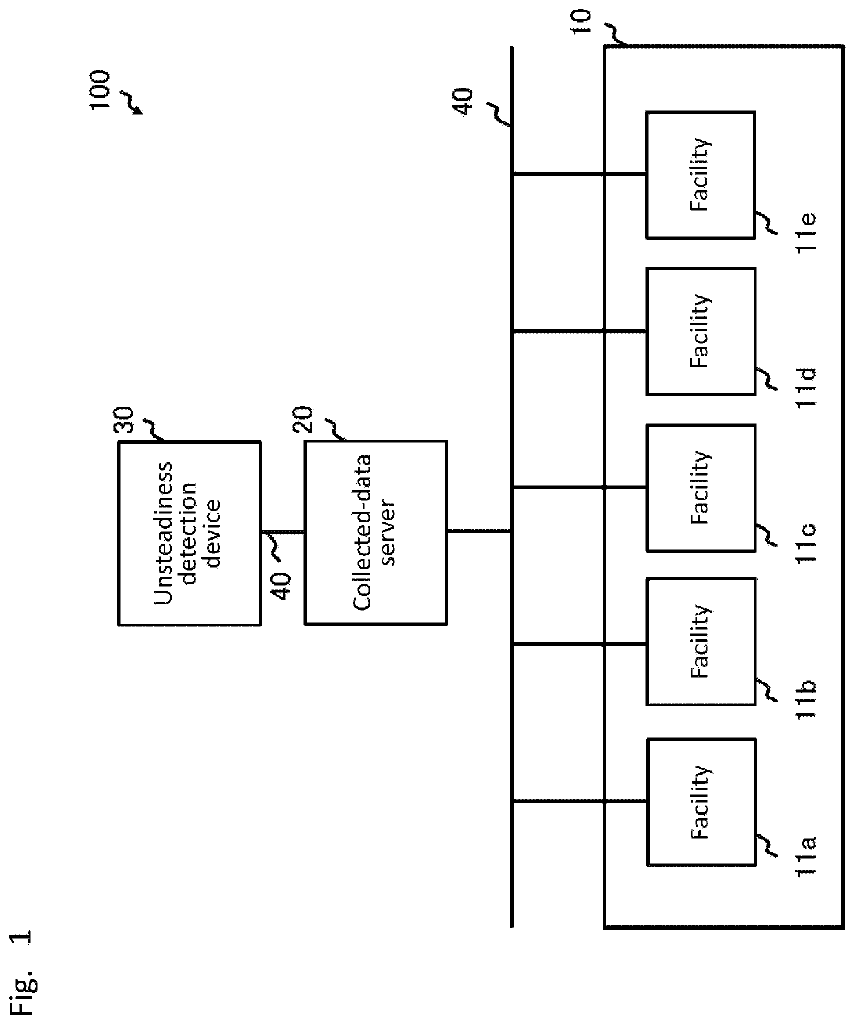
[0025]FIG. 1 is a configuration diagram example of an unsteadiness detection system according to Embodiment 1 of the present invention. As shown in FIG. 1, the unsteadiness detection system 100 includes a factory line 10 including five facilities 11 (11a to 11e), a collected-data server 20, an unsteadiness detection device 30 and a network 40.

[0026]Each facility 11 is a processing device such as an injection molder, an extruder, a lathe and a grinder, or a control device such as a servo amplifier and a programmable logic controller (PLC), and the facility includes a component such as a switch, a relay, a sensor or a digital circuit to output a binary digital signal, and is controlled by binary digital signals.

[0027]The collected-data server 20 includes a storage unit and obtains operation data as binary digital signals from the five facilities 11 connected in the factory line 10, to accumulate them in storage unit. The operation data include opening / closing information of switches o...

embodiment 2

[0103]In Embodiment 1, a method for detecting the operation state of a facility 11 using binary digital signals was described. In Embodiment 2, another embodiment will be described in which the operation state of the facility 11 is detected and the user is, when the operation state is unsteady, notified of the cause of the detected unsteadiness of the operation state. In addition, the configuration of an unsteadiness detection system 100, the structure of an unsteadiness detection device 30, the structure of a control device 31 of an unsteadiness detection device 30, and the normal model generation processing performed by the control device 31 are the same as those in Embodiment 1, therefore their descriptions will be omitted.

[0104]FIG. 12 is a functional configuration diagram example of an unsteadiness detection processing according to Embodiment 2 of the present invention. The difference from the functional configuration for performing the unsteadiness detection processing in Embo...


PUM


Abstract

An unsteadiness detection device (30) is provided which is capable of detecting the operation state of facilities using binary digital signals, the unsteadiness detection device including: a model generation unit (313) to generate a normal model for determining operation states of a plurality of facilities (11) on the basis of operation data which are binary digital signals obtained from the facilities (11) in their steady operation states; an expectation value calculation unit (315) to calculate an expectation value of operation data by applying the normal model to past operation data of the facilities (11); and an unsteadiness detection unit (316) to detect whether or not an operation state of one of the facilities (11) is unsteady by comparing the expectation value of the operation data and a measured value of the operation data.

Description

TECHNICAL FIELD[0001]The present invention relates to an unsteadiness detection system for detecting unsteady states of facilities connected in a factory automation system (hereinafter, referred to as the FA system).BACKGROUND ART[0002]Conventionally, in a site for manufacturing products such as a factory, when a facility having normally operated falls from a steady state to an unsteady state, i.e. for example to a case of stoppage of a manufacturing line, a maintenance worker in charge of the facility of the manufacturing line identifies the cause of the trouble and takes an action such as replacing a part to get rid of the anomaly, restoring a steady operation state of the facility from the unsteady state one.[0003]However, as facilities in a factory get complicated due to for example introduction of an FA system, maintenance workers have to acquire an enormous amount of knowledge and knowhow. In this situation, the maintenance workers with less experience often face difficulties ...

Claims


Application Information

Patent Timeline
IPC IPC(8): G05B23/02G06N20/00
CPCG06N20/00G05B23/0243G05B13/02G05B23/02G06F11/3013G06F11/3055G06F11/3447G06F11/3452G05B19/4184G05B23/024
Inventor SHIBATA, MASAHIKOSHIRAKI, KENGONAKAHARA, DAIKI
Owner MITSUBISHI ELECTRIC CORP
Why Eureka
Try Eureka