Resistive heater

a technology of resistive heating and heaters, which is applied in the direction of non-metal conductors, conductors, sustainable buildings, etc., can solve the problem that resistive heaters do not provide for evenly distributed hea

Inactive Publication Date: 2016-01-21
ELVERUD KIM EDWARD
View PDF3 Cites 28 Cited by
  • Summary
  • Abstract
  • Description
  • Claims
  • Application Information

AI Technical Summary

Benefits of technology

[0006]The following presents a simplified summary of one or more embodiments of the present disclosure in order to provide a basic understanding of such embodiments. This summary is not

Problems solved by technology

In many cases, resistive heaters do not provide for evenly distributed heat throughout a heating

Method used


Image

  • Resistive heater
  • Resistive heater
  • Resistive heater

Examples


Embodiment Construction

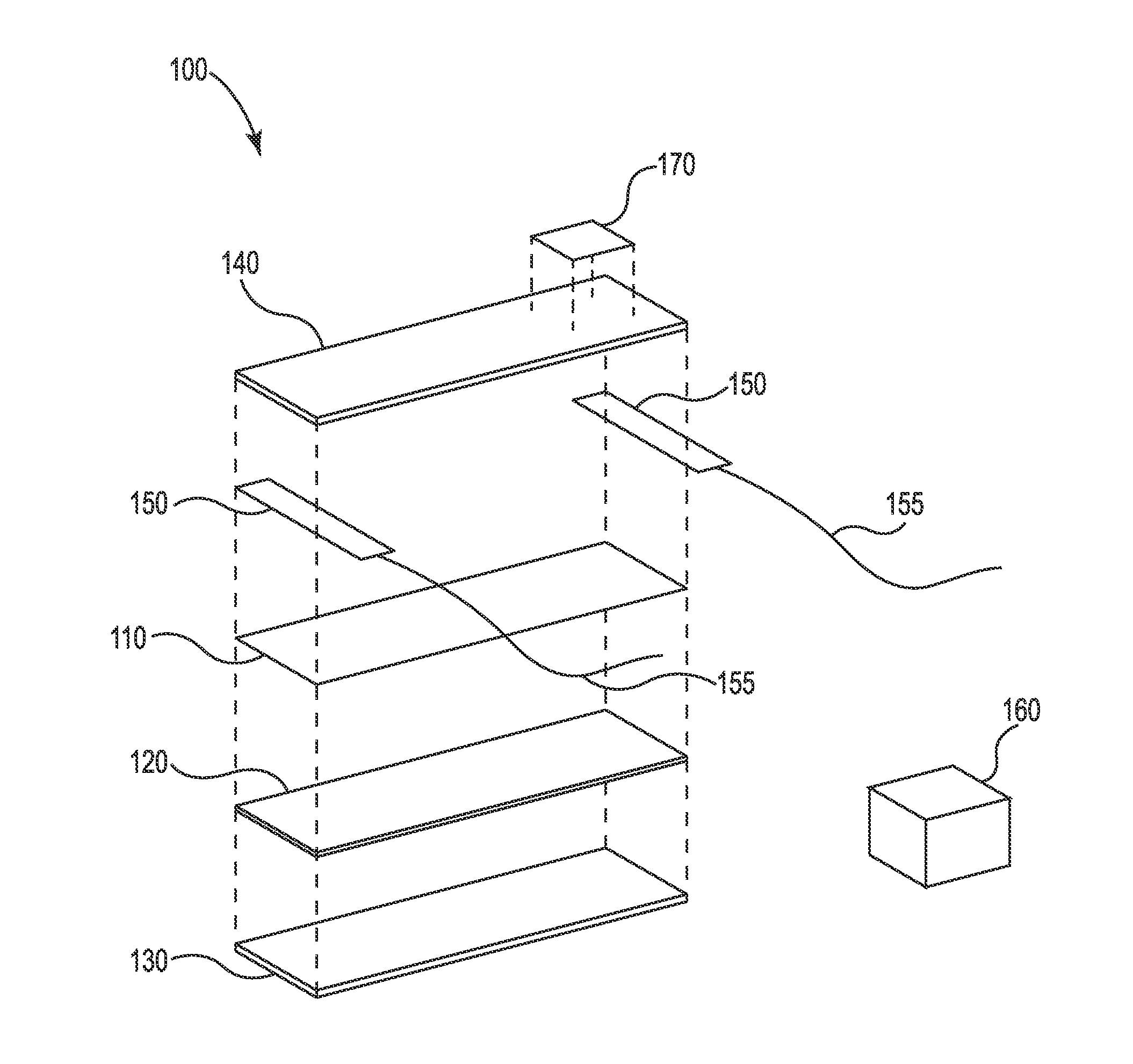
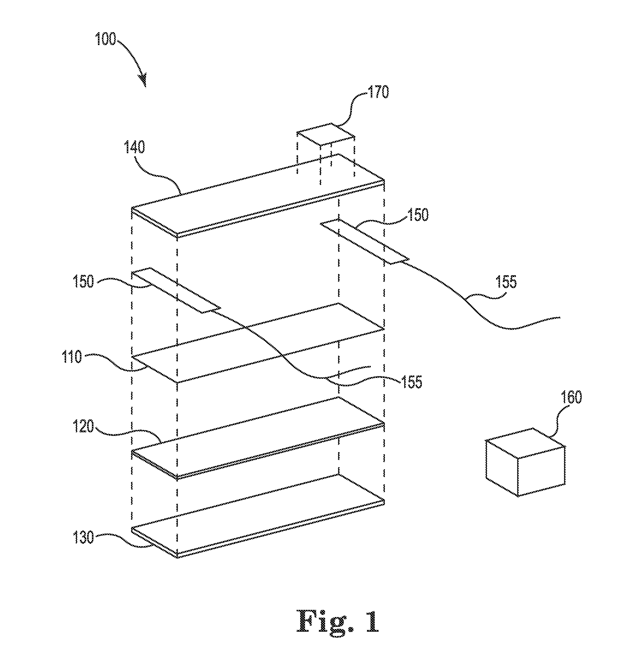
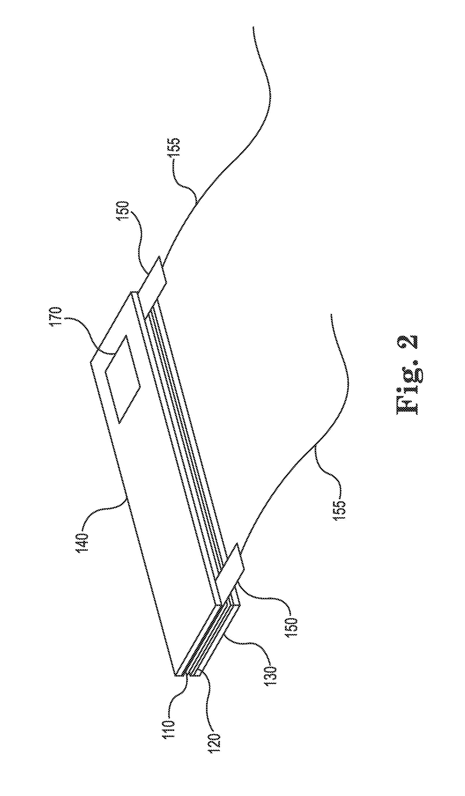
[0018]The present disclosure relates to novel and advantageous composite formulations for use in resistive heaters. The present disclosure additionally relates to novel and advantageous resistive heaters utilizing a composite layer.

[0019]For purposes of the present disclosure:[0020]The term “thermal conductivity,” along with any other conventional definition or understanding by one of skill in the art, is meant to include the ease with which thermal energy is conducted from one component to another component.[0021]The term “thermal emissivity,” along with any other conventional definition or understanding by one of skill in the art, is meant to include the ease with which thermal energy is radiated from one component to another item.[0022]The term “electrical conductivity,” along with any other conventional definition or understanding by one of skill in the art, is meant to include the ease with which electrical energy is conducted from one component to another component.[0023]The t...


PUM


Abstract

A composite formulation of the present disclosure may have conductive properties (i.e. low resistance), such that the formulation may be used in resistive heating applications. The composite may have one or more matrix materials and one or more conductive fillers. The composite may be used in the formation of resistive heaters having a number of layers, including a conductive layer, the conductive layer including the composite. Heaters of the present disclosure may be used for a number of applications including ground, floor, or roof heating, or laboratory equipment heating.

Description

CROSS-REFERENCE TO RELATED APPLICATIONS[0001]The present application claims priority to U.S. Provisional Patent Application No. 62 / 026,203 filed on Jul. 18, 2014, entitled Resistive Heater, the content of which is hereby incorporated by reference herein in its entirety.FIELD OF THE INVENTION[0002]The present disclosure relates to composite formulations for use in resistive heating. Particularly, the present disclosure relates to composite formulations having one or more conductive fillers for use in resistive heating. Additionally, the present disclosure relates to resistive heaters having a composite layer.BACKGROUND OF THE INVENTION[0003]The background description provided herein is for the purpose of generally presenting the context of the disclosure. Work of the presently named inventors, to the extent it is described in this background section, as well as aspects of the description that may not otherwise qualify as prior art at the time of filing, are neither expressly nor impl...

Claims


Application Information

Patent Timeline
IPC IPC(8): H05B3/00H01B1/24H05B3/02H05B3/14H05B3/18
CPCH05B3/0014H05B3/026H01B1/24H05B3/18H05B3/02H05B3/145H05B3/34H05B3/58H05B2203/011H05B2214/04Y02B10/30
Inventor ELVERUD, KIM, EDWARD
Owner ELVERUD KIM EDWARD
Why Eureka
Try Eureka