Rader level gauge

a level gauge and radar technology, applied in waveguide horns, instruments, and using reradiation, etc., can solve the problems of limited freedom in designing the transmitter receiver circuit board, large transmission losses, and difficult to minimize the horizontal size of the level gauge, so as to reduce transmission losses, minimize horizontal size of the radar level gauge, and smooth vary

Active Publication Date: 2016-02-11
TOKYO KEIKI
View PDF8 Cites 10 Cited by
  • Summary
  • Abstract
  • Description
  • Claims
  • Application Information

AI Technical Summary

Benefits of technology

[0017]According to the present invention, the transmitter receiver circuit board is so disposed in the housing as to extend vertically, so that the horizontal size of the radar level gauge may be minimized. In addition, the connection arrangement includes a waveguide sequence, in which the vertically extending transmitter receiver circuit board and the antenna unit are connected by means of the circular waveguide, the rectangular waveguide, and a second circular waveguide, so that transmission losses may be suppressed and reduced, and the propagation direction of the electromagnetic signals may be smoothly varied from horizontal to vertical.
[0018]The position of the feed terminal formed on the transmitter receiver circuit board is not necessarily required to be at the center of the circuit board. Rather, the feed terminal may be provided at any position on the transmitter receiver circuit board as long as the position of the circular waveguide and the position of the feed terminal correspond to each other, leading to enhanced freedom in selection of the position of the feed terminal on the transmitter receiver circuit board.
[0019]By virtue of the provision of the dielectric body disposed in the waveguide sequence at and over the boundary between the rectangular waveguide and the second circular waveguide, reflection at the transition point between the rectangular waveguide and the second circular waveguide may be advantageously suppressed. In addition, in the case where the insulation dielectric body is provided in order to achieve electrical isolation between the ground conductor of the transmitter receiver circuit board and the housing at the boundary between the rectangular waveguide and the second circular waveguide, leakage of electromagnetic signals from the waveguide sequence and reflection in the waveguide sequence may be advantageously suppressed.

Problems solved by technology

Since the radar level gauge of Patent Document No. 1 has the transmitter receiver circuit board so disposed as to extend horizontally, the level gauge disadvantageously occupies a relatively large horizontal area when mounted in position and it is difficult to minimize the horizontal size of the level gauge.
In addition, with this known radar level gauge, the position of the hole formed in the transmitter receiver circuit board for receiving one end of the central conductor is limited to be adjacent to the center of the circuit board, which disadvantageously leads to limited freedom in designing the transmitter receiver circuit board.
On the other hand, however, the use of the coaxial line disadvantageously tends to lead to relatively large transmission losses.
In addition, the use of the coaxial line also disadvantageously tends to cause reflection of electromagnetic signals at the connection point (or the feed point) between the coaxial line and the antenna unit.

Method used


Image

  • Rader level gauge
  • Rader level gauge
  • Rader level gauge

Examples


Embodiment Construction

[0028]Hereinafter, an embodiment of the present invention will be described with reference to the accompanying drawings.

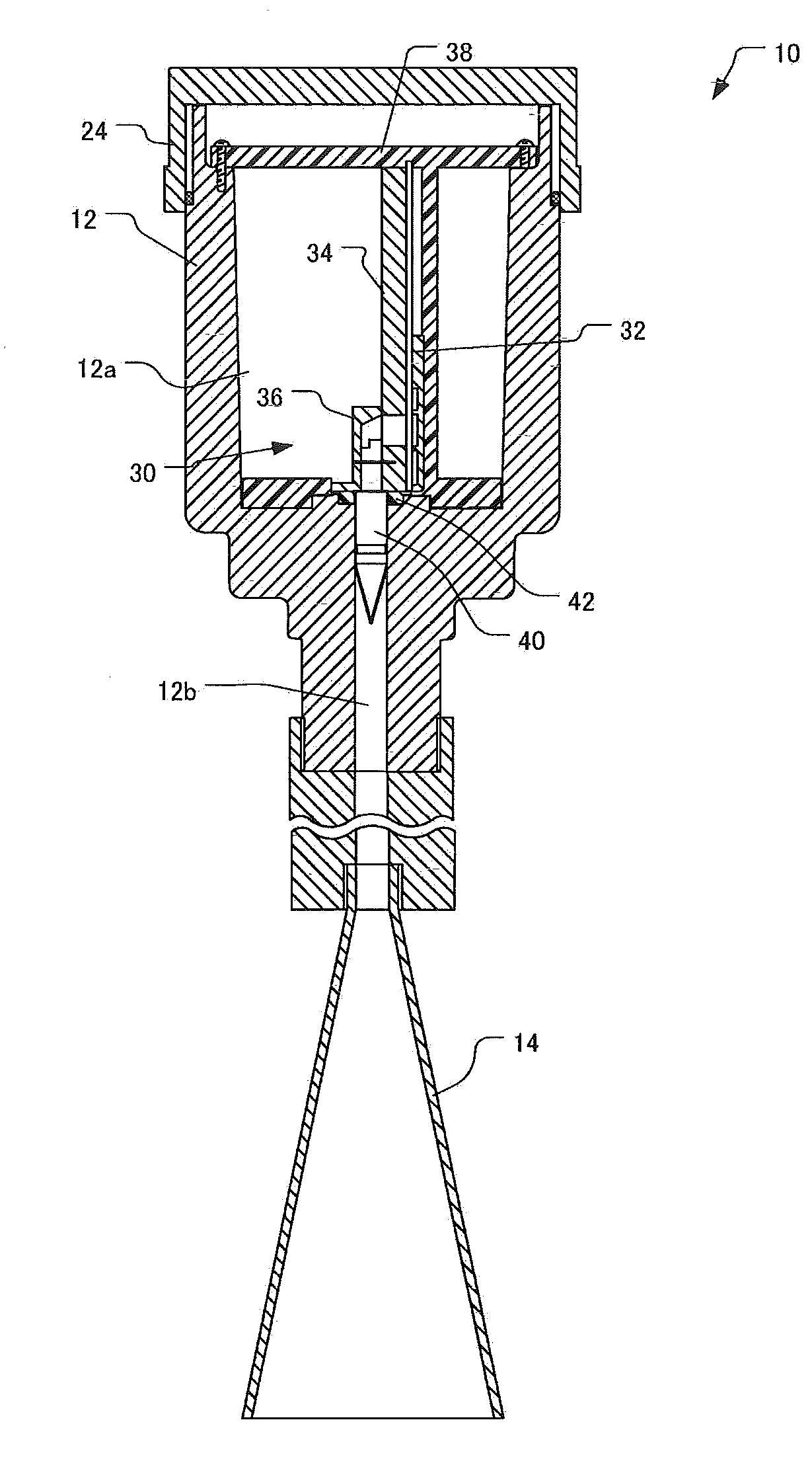
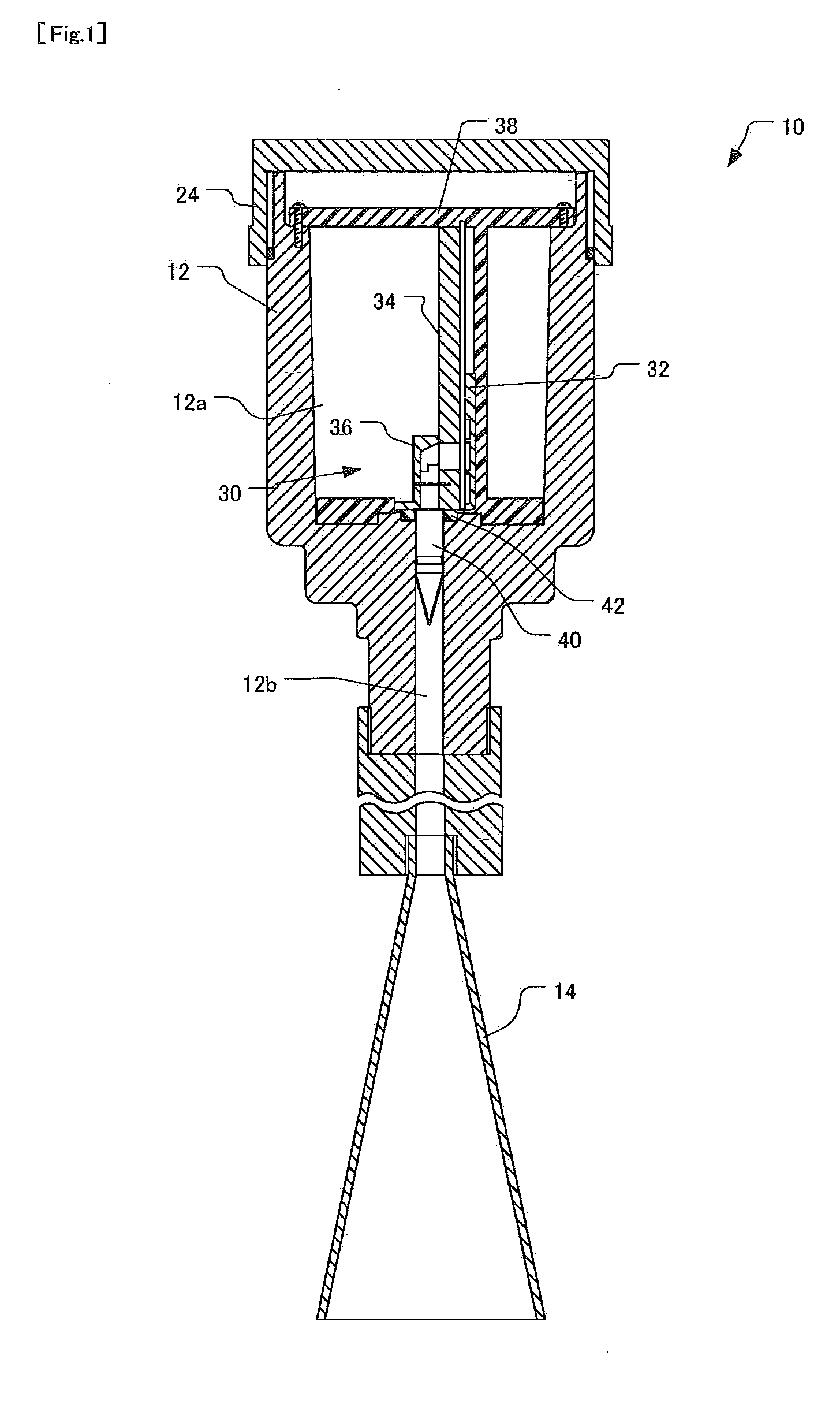
[0029]In general, as shown in FIGS. 1 and 2, a radar level gauge 10 in accordance with an embodiment of the present invention includes a housing 12 forming an upper portion of the radar level gauge 10 and an antenna unit 14 forming a lower portion of the radar level gauge 10. The housing 12 is made of a metallic material. The antenna unit 12 transmits electromagnetic signals from a tip end (lower end) thereof toward a measurement object contained in a container. The traveling time of the transmitted electromagnetic signals reflected by the measurement object is measured to determine the distance between the radar level gauge 10 and the measurement object, and thus to determine the filling level of the measurement object in the container. In the following description, with regard to several elements disposed between the housing 12 and the antenna unit 14, a first en...


PUM


Abstract

A radar level gauge using electromagnetic signals is provided, which includes a connection arrangement for connecting a transmitter receiver circuit board and an antenna unit with one another, with which the horizontal size of the radar level gauge may be reduced and reflection and transmission losses may be suppressed as well. The transmitter receiver circuit board 32 is so disposed in a housing 12 as to extend vertically. The connection arrangement includes a waveguide sequence which is fed at a feed terminal 32a formed on the transmitter receiver circuit board 32 and composed of three waveguides W1 to W3. Specifically, the waveguide sequence includes, in sequential order from the transmitter receiver circuit board to the antenna unit: a circular waveguide W1 extending horizontally and perpendicular to the transmitter receiver circuit board; a rectangular waveguide W2 in connection with the circular waveguide W1 and extending vertically; and a second circular waveguide W3 further in connection with the rectangular wave guide W2 and extending vertically.

Description

TECHNICAL FIELD[0001]The present invention relates to a rader level gauge for measuring level of a measurement object by means of electromagnetic signals, and in particular, to a radar level gauge including a transmitter receiver circuit board accommodated in a housing, an antenna unit for transmitting and receiving electromagnetic signals, and a connection arrangement for connecting the transmitter receiver circuit board and the antenna unit with one another.BACKGROUND OF THE INVENTION[0002]A typical radar level gauge described above includes a transmitter receiver circuit board accommodated in a housing and having transmitter receiver circuitry mounted thereon, and an antenna unit extending vertically into a container, in which a measurement object is contained, in order to determine a level of a object by transmit electromagnetic signals and receive the reflected signals. For connecting the transmitter receiver circuit board and the antenna unit with one another, a connection arr...

Claims


Application Information

Patent Timeline
Patent Type & Authority Applications(United States)
IPC IPC(8): G01F23/284
CPCG01F23/284H01P5/087H01P5/107H01Q1/225H01Q13/02
Inventor ITO, SATOSHIKISHIMOTO, MASAOHOTTA, AKIRA
Owner TOKYO KEIKI
Why Eureka
Try Eureka