Leak indicator

Active Publication Date: 2016-02-11
BEERENBERG CORP
View PDF6 Cites 0 Cited by
  • Summary
  • Abstract
  • Description
  • Claims
  • Application Information

AI Technical Summary

Benefits of technology

The apparatus helps to detect liquid leaks, and it has a hood to protect it from water and other liquids that might contaminate the sample. This prevents false readings and ensures accurate detection.

Problems solved by technology

Such insulation may however be problematic as it significantly impedes inspection of the underlying structure and tends to collect and maintain moisture and humidity.
Rust and corrosion is a particular problem.
Electricity may be problematic to use, in particular on installations where explosion hazards are present.
Such systems will typically only provide an indication of the presence of a liquid, but not a liquid sample.

Method used


Image

  • Leak indicator
  • Leak indicator
  • Leak indicator

Examples


embodiments

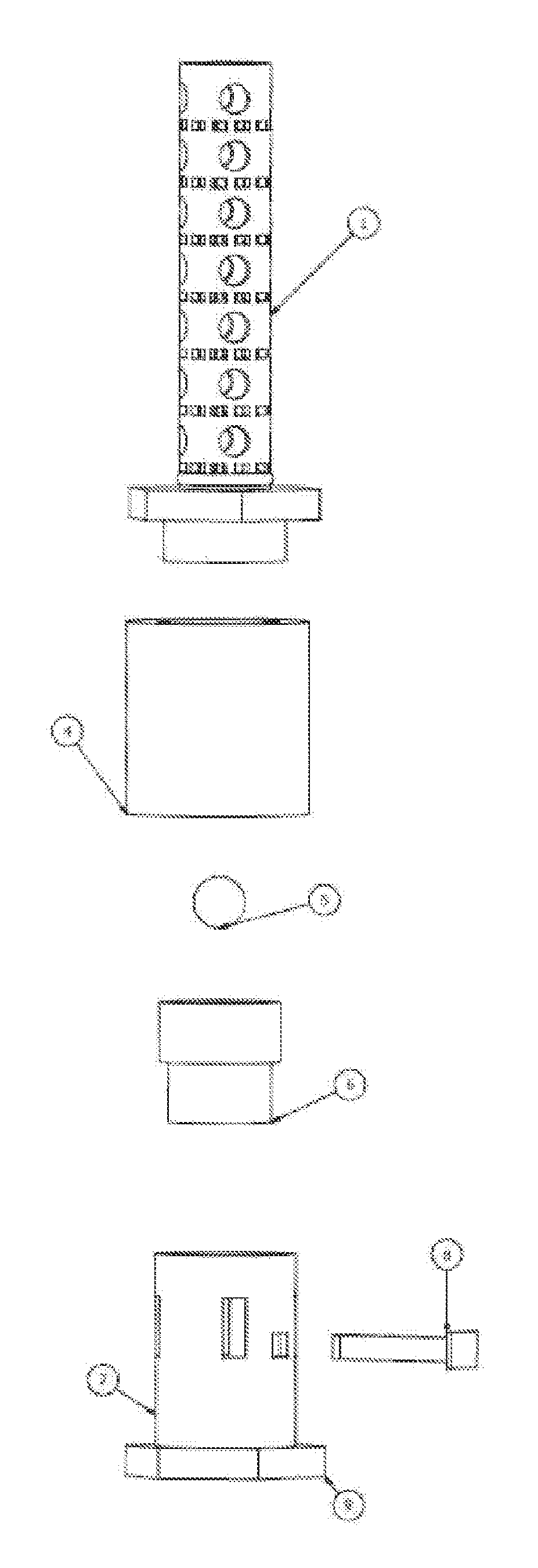
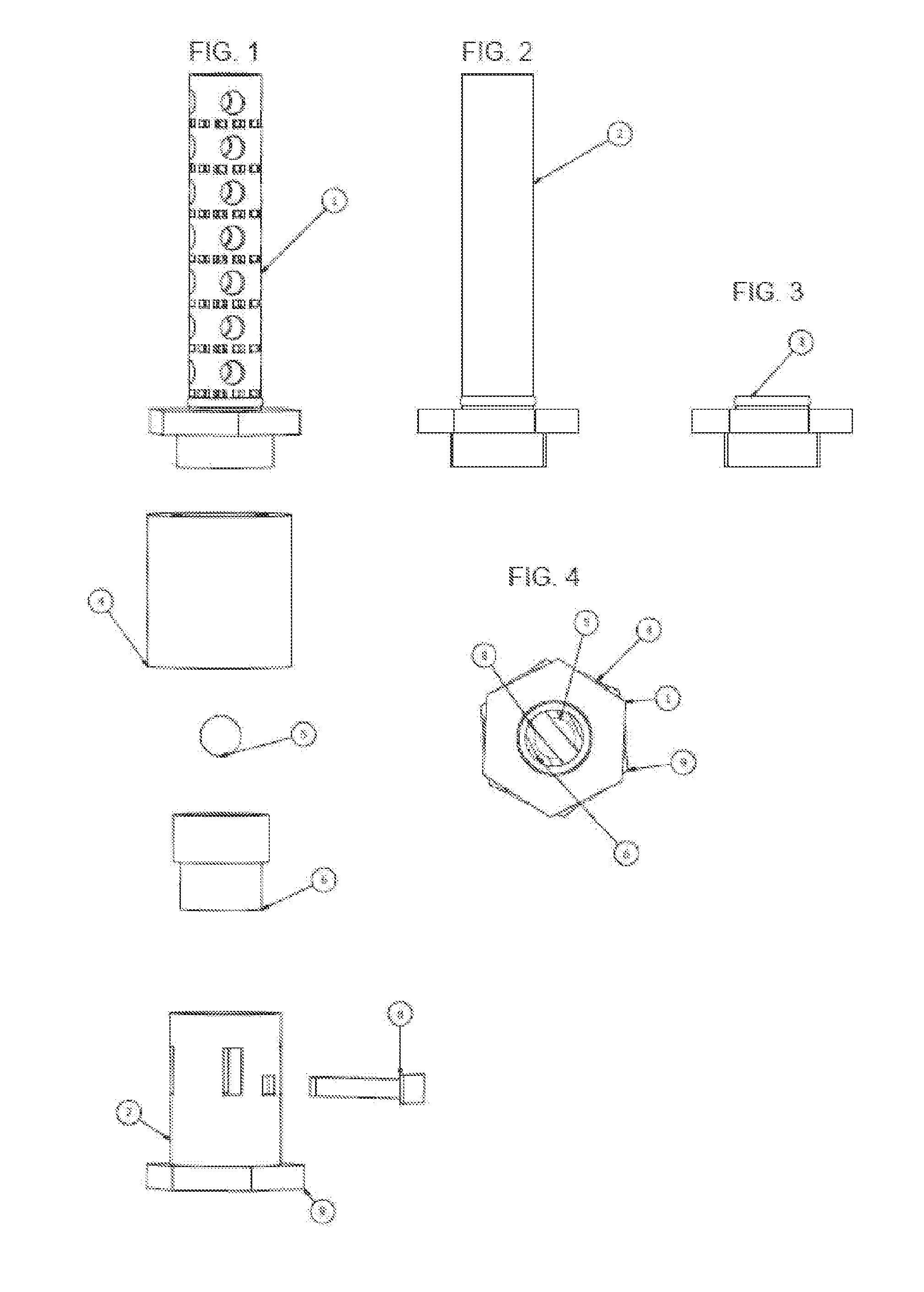
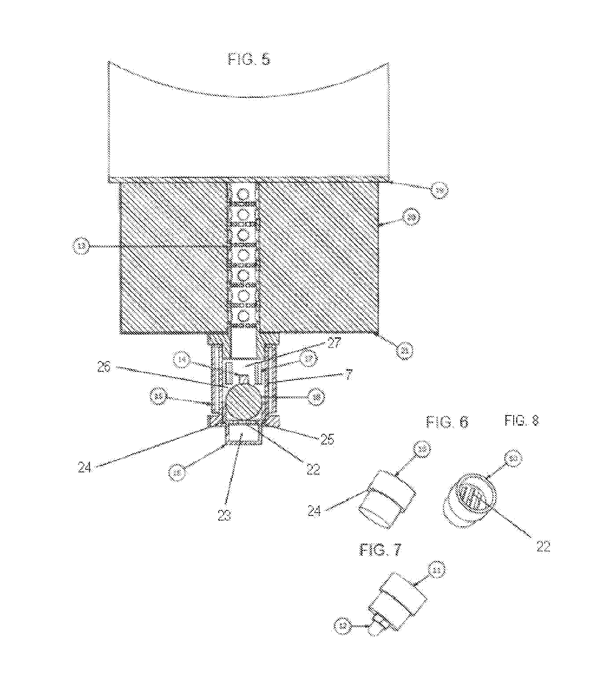
[0033]FIG. 1 is an exploded view of a first embodiment of a leakage detection apparatus. The leakage detection apparatus includes a drain pipe 1 to collect fluid from the structure to be monitored, a hood 4 to prevent unwanted water penetration from the surroundings, a ball 5 of a hydrophilic elastomeric that expands upon contact with fluid, an indicator body 6, a sleeve shaped housing 7 with inner treads and a hex nut 9 for assembly and disassembly, and a lock pin 8.

[0034]The drain pipe 1 may be adapted for different uses and materials. In an application with a pipe inside a porous insulating material, the drain pipe will typically be designed as a perforated pipe with perforations for allowing liquid to seep into the plug and flow down to the ball 5 of a hydrophilic elastomer. The drain pipe 1 should therefore preferably be installed vertically or close to vertically to ensure that the liquid flows down to the ball 5 of a hydrophilic elastomer.

[0035]The drain pipe 1 of the embodim...


PUM


Abstract

The present invention concerns a liquid leakage detection apparatus. The apparatus includes a sample cavity, a housing with an opening and a housing contact face, an indicator body with an indicator body contact face, and a expansion element cavity between said housing contact face and said indicator body contact face. A liquid sensitive, expandable element is located in the expansion element cavity and a liquid path extends between the liquid collecting portion and the expansion element cavity.

Description

[0001]This application is a national phase entry of International Application No. PCT / NO2014 / 050042, entitled “LEAK INDICATOR”, filed on Mar. 24, 2013, and claims priority to Norwegian Patent Application No. 20130423 filed Mar. 25, 2013, the disclosure of each being hereby incorporated by reference in its entirety herein.BACKGROUND[0002]The present disclosure relates to a leak indicator for indicating leaks in insulating layers and other elements where an indication of liquid leaks is desired or required, and for sampling leaked liquid for further investigation.[0003]Insulated pipelines, vessels, and steel structures are common in the process industry, on offshore installations, on vessels etc. Such insulation is common to reduce heat loss from the structure, to provide improved fire resistance for the structure, to reduce safety issues of hot surfaces and other reasons. Such insulation may however be problematic as it significantly impedes inspection of the underlying structure and...

Claims


Application Information

Patent Timeline
IPC IPC(8): G01M3/04
CPCG01M3/04G01M3/042
Inventor HARRIS, GEIRLYGRE, OLAV BJORN
Owner BEERENBERG CORP
Why Eureka
Try Eureka