DC power distrubution system

a technology of dc power distribution and direct current, which is applied in the direction of power distribution line transmission, data switching details, data switching current supply, etc., can solve the problem of tedious task of commissioning large electrical loads, and achieve the effect of convenient commissioning of electrical loads

Inactive Publication Date: 2016-02-11
SIGNIFY HLDG BV
View PDF1 Cites 12 Cited by
  • Summary
  • Abstract
  • Description
  • Claims
  • Application Information

AI Technical Summary

Benefits of technology

[0003]It is an object of the present invention to provide a DC power distribution system having a power supply module, several power conductors electrically connected to the power supply module and several electrical loads electrically connected to the power conductors, which allows for an easier commissioning of the electrical loads.
[0008]Different groups of ports correspond therefore to different power line communication universes, i.e. power line communication signals can be separately addressed to the different groups of ports. Electrical loads electrically connected to power conductors, which are electrically connected to different groups of ports of the power supply module, are therefore, regarding the power line communication, separated from each other. This allows determining to which group of ports which electrical loads are electrically connected depending on power line communication identification signals received via the respective power line communication channel. This information can be used by, for instance, a user to commission the electrical loads. For example, if the locations of the power conductors, which are electrically connected to certain groups of ports, are known, the information to which group of ports a respective electrical load is electrically connected can be used for determining the location of the respective electrical load. In particular, if it is known that power conductors connected to a certain group of ports are located within a certain room, it can be determined which electrical loads are located in this room based on the information provided by the electrical loads determination unit. Moreover, at least regarding one power line communication channel several electrical loads are in power line communication with a group of ports of a same power line communication channel such that these electrical loads can be regarded as forming a group of electrical loads. Since the power line communication channels are separated, it can easily be detected which electrical loads belong to this group.
[0018]Preferentially, the power line communicator is integrated with the power supply module. It may therefore not be necessary to install an additional power line communicator, which can simplify the installation of the DC power distribution system. However, the power line communicator may also be a separate device, wherein the power supply module and the power line communicator may be adapted such that the power line communicator is internally or externally addable to the power supply module. The power line communicator can also be a separate device directly electrically connectable to a power conductor, in order to receive power line communication identification signals from the power conductor. In particular, the system can comprise several power line communicators, i.e. for each group of ports a power line communicator, wherein each power line communicator is electrically connected to a power conductor, which is electrically connected to the respective group of ports, in order to receive the power line communication identification signals from the electrical loads electrically connected—via one or several power conductors—to the respective group of ports.
[0020]In a further embodiment the power line communicator is integrated in an electrical connector to be connected to a power conductor. The electrical connector may just be an electrical connector of an electrical load or of another device to be connected to a power conductor such that it may not be necessary to additionally add power line communicators to the power conductors, which may simplify the installation of the DC power distribution system. The electrical connector may also be an electrical connector with the integrated power line communicator, without connecting a further device to the power conductor.
[0022]In a preferred embodiment the system comprises at least two power line communicators connected to at least two different groups of ports, wherein the at least two power line communicators are adapted to concurrently receive power line communication identification signals. In particular, to each group of ports a power line communicator may be assigned such that for all groups of ports power line communication identification signals can be received in parallel. This increases the speed of the discovery procedure.
[0023]The power line communicator may comprise a user switch for allowing a user to define which electrical load belongs to which power line communication channel. For instance, if the system comprises several power conductors, wherein to each power conductor electrical loads are attached and wherein to each power conductor a respective power line communicator is in power line communication, the power line communicators may be connected to each other and each power line communicator may comprise a user switch allowing the user to define to which power line communication channel the respective power conductor and correspondingly the electrical loads attached to the respective power conductor should belong. For instance, the user switch may be adapted to allow a user to choose between power line communication channels A, B, C, D, wherein for each power conductor the user can define to which of these power line communication channels A, B, C, D the respective power conductor and the attached electrical loads should belong. This allows the user to merge two or more power conductors to a single power line communication channel, if these power conductors have been selected by the user as belonging to the same power communication channel. The user switches can therefore be adapted to allow a user like an installer to separate and merge power line communication channels as desired during or after installation.

Problems solved by technology

Commissioning the large amount of electrical loads is a tedious task.

Method used


Image

  • DC power distrubution system
  • DC power distrubution system
  • DC power distrubution system

Examples


Embodiment Construction

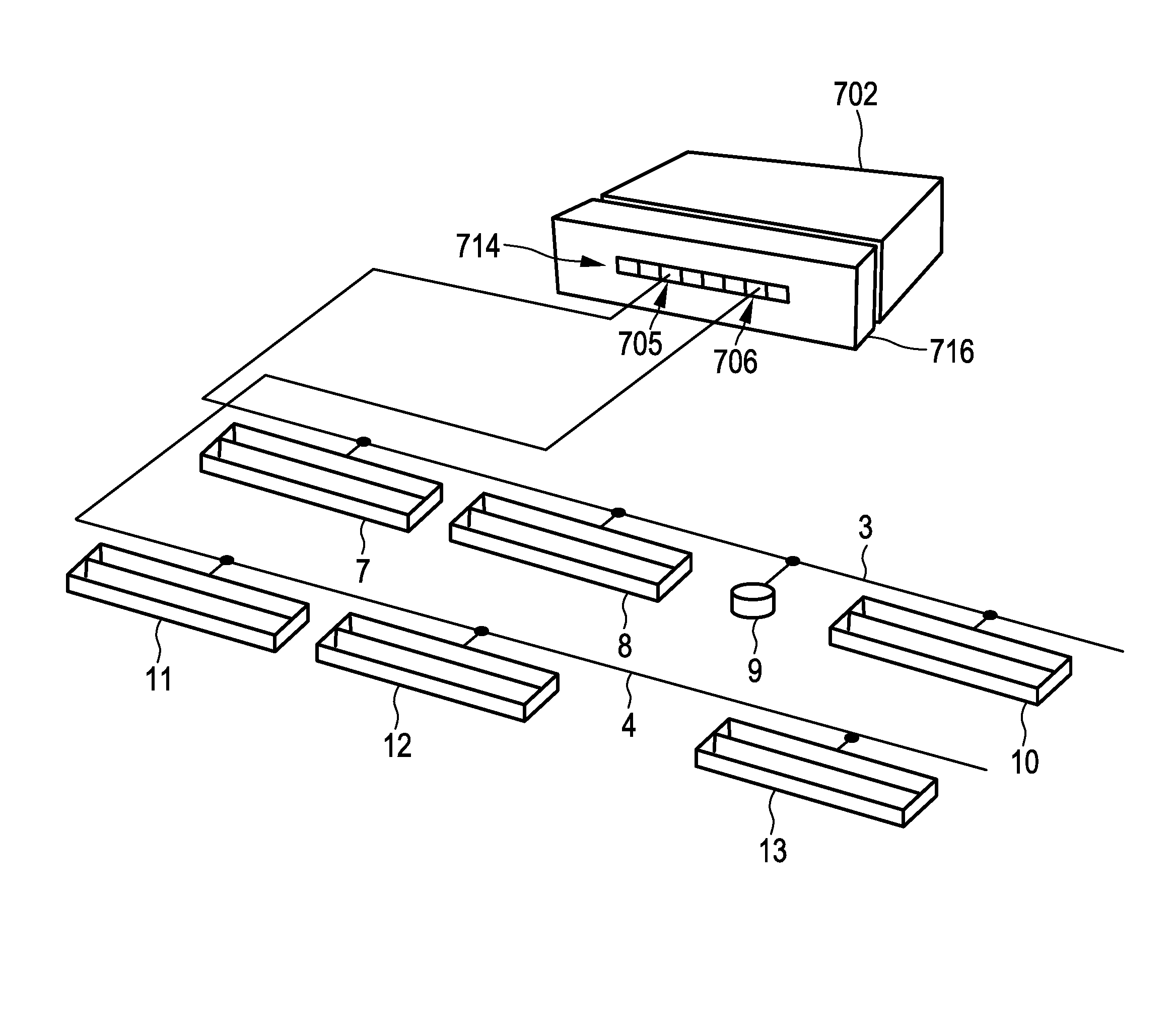
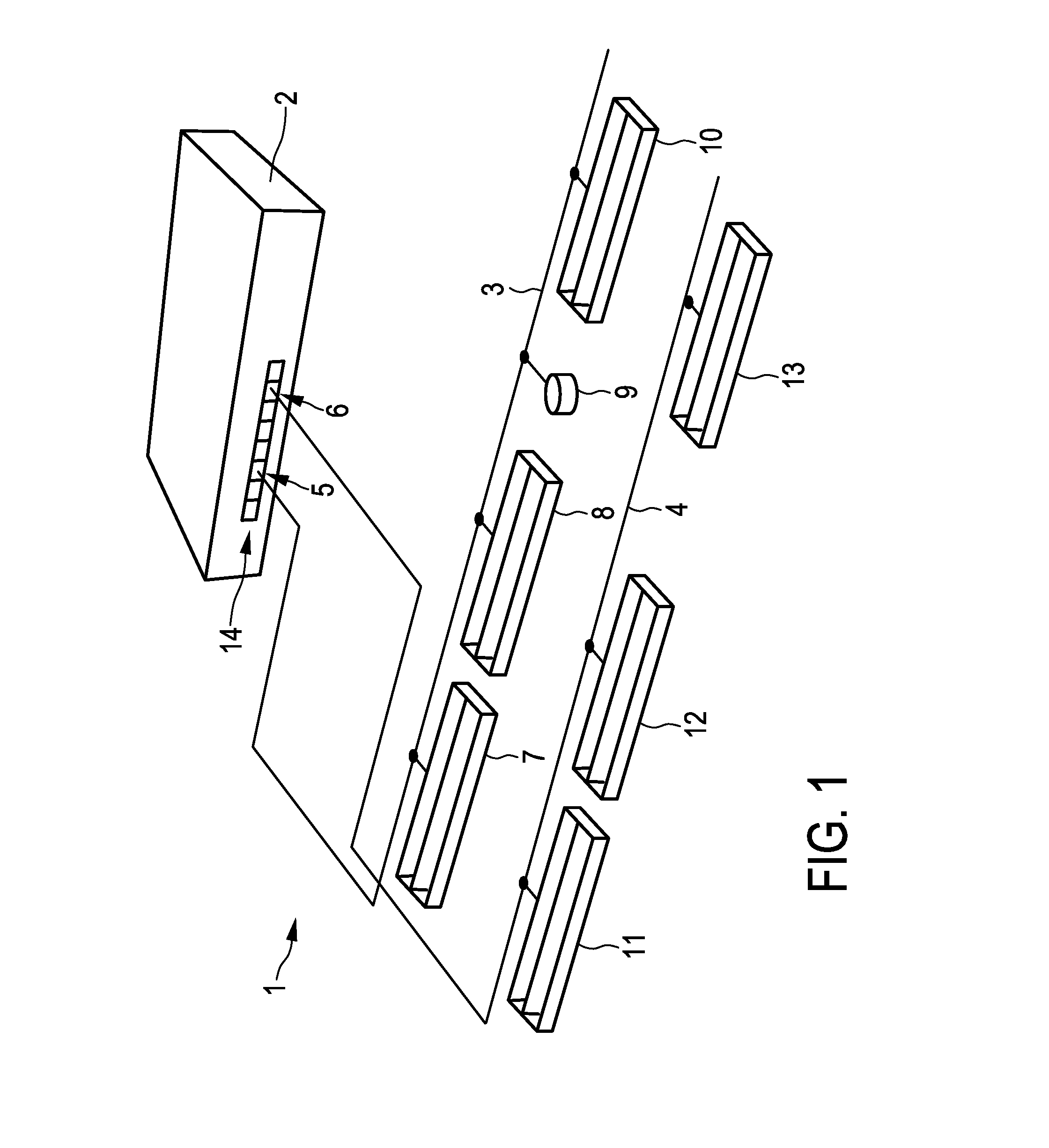
[0047]FIG. 1 shows schematically and exemplarily an embodiment of a DC power distribution system. The DC power distribution system 1 comprises a power supply module 2 having several groups of ports 14 for providing DC power, wherein in this embodiment each group comprises a single port only. The DC power distribution system 1 further comprises several bus bars 3, 4 electrically connected to the several groups of ports for distributing the DC power. In this embodiment a bus bar 4 is electrically connected to the port 6 and another bus bar 3 is electrically connected to the port 5. Several electrical loads 7 . . . 13 are electrically connected to the bus bars 3, 4, wherein the electrical loads 7 . . . 13 are adapted to send power line communication identification signals, which are indicative of the respective electrical load 7 . . . 13, over the bus bars 3, 4. In this embodiment two kinds of electrical loads are electrically connected to the bus bars 3, 4, lighting devices 7, 8, 10 ....


PUM


Abstract

The invention relates to a DC power distribution system, especially an EMerge DC power distribution system (1). The system is adapted such that power conductors (3, 4) electrically connected to different groups (5, 6) of ports (14) belong to separate power line communication (PLC) channels, wherein several electrical loads (7 . . . 10; 11 . . . 13) are in power line communication with a group of ports of a same PLC channel. The separation of the different PLC channels allows for a relatively simple determination to which group of ports which electrical loads are electrically connected. This information can be used by, for instance, a user to commission the electrical loads. For example, if the locations of the power conductors, which are electrically connected to certain groups of ports, are known, the information about which electrical loads are connected to which groups of ports can be used for determining the location of the respective electrical load.

Description

FIELD OF THE INVENTION[0001]The invention relates to a direct current (DC) power distribution system for distributing DC power from a power supply module to electrical loads.BACKGROUND OF THE INVENTION[0002]Version 1.1 of the EMerge Occupied Space standard defines a DC power distribution system having a power supply module, several bus bars electrically connected to the power supply module and several electrical loads electrically connected to the bus bars, in order to receive DC power from the power supply module via the bus bars. The DC power distribution system may be installed at a ceiling of a room, where a large amount of different electrical loads like several light devices, sensors or other electrical consumers may be electrically connected to the bus bars. Commissioning the large amount of electrical loads is a tedious task. For instance, a user like an installer may need to check for each electrical load where it is located.SUMMARY OF THE INVENTION[0003]It is an object of ...

Claims


Application Information

Patent Timeline
Patent Type & Authority Applications(United States)
IPC IPC(8): H04L12/10H02J1/00
CPCH02J1/00H04L12/10H04B3/548H04B2203/547
Inventor WENDT, MATTHIASERDMANN, BOZENAALARCON-RIVERO, MANUEL EDUARDODRAAIJER, MAURICE HERMAN JOHAN
Owner SIGNIFY HLDG BV
Why Eureka
Try Eureka