Flow meter having a background pattern with first and second portions

a flow meter and background pattern technology, applied in the field of flow meter, can solve the problems of changing the size of the lumen, the pump may not be used in all situations or environments, etc., and achieve the effect of reducing the internal volume of the tub

Active Publication Date: 2016-03-03
DEKA PROD LLP
View PDF1 Cites 129 Cited by
  • Summary
  • Abstract
  • Description
  • Claims
  • Application Information

AI Technical Summary

Benefits of technology

The invention relates to an IV adminination set with a flexible tube, two ports, and a curved support member which can be compressed or extended to change its length. This design allows for easy handling and adjustment of the size of the tubular space through which fluids are directed during use.

Problems solved by technology

The technical problem addressed in this patent text is the need for a medical treatment that involves delivering fluids into a patient, either quickly, accurately, or slowly, using a gravity-fed line and adjusting the flow rate through a valve. This method may not always be suitable for all situations or environments, so an infusion pump may be used instead.

Method used


Image

  • Flow meter having a background pattern with first and second portions
  • Flow meter having a background pattern with first and second portions
  • Flow meter having a background pattern with first and second portions

Examples


Embodiment Construction

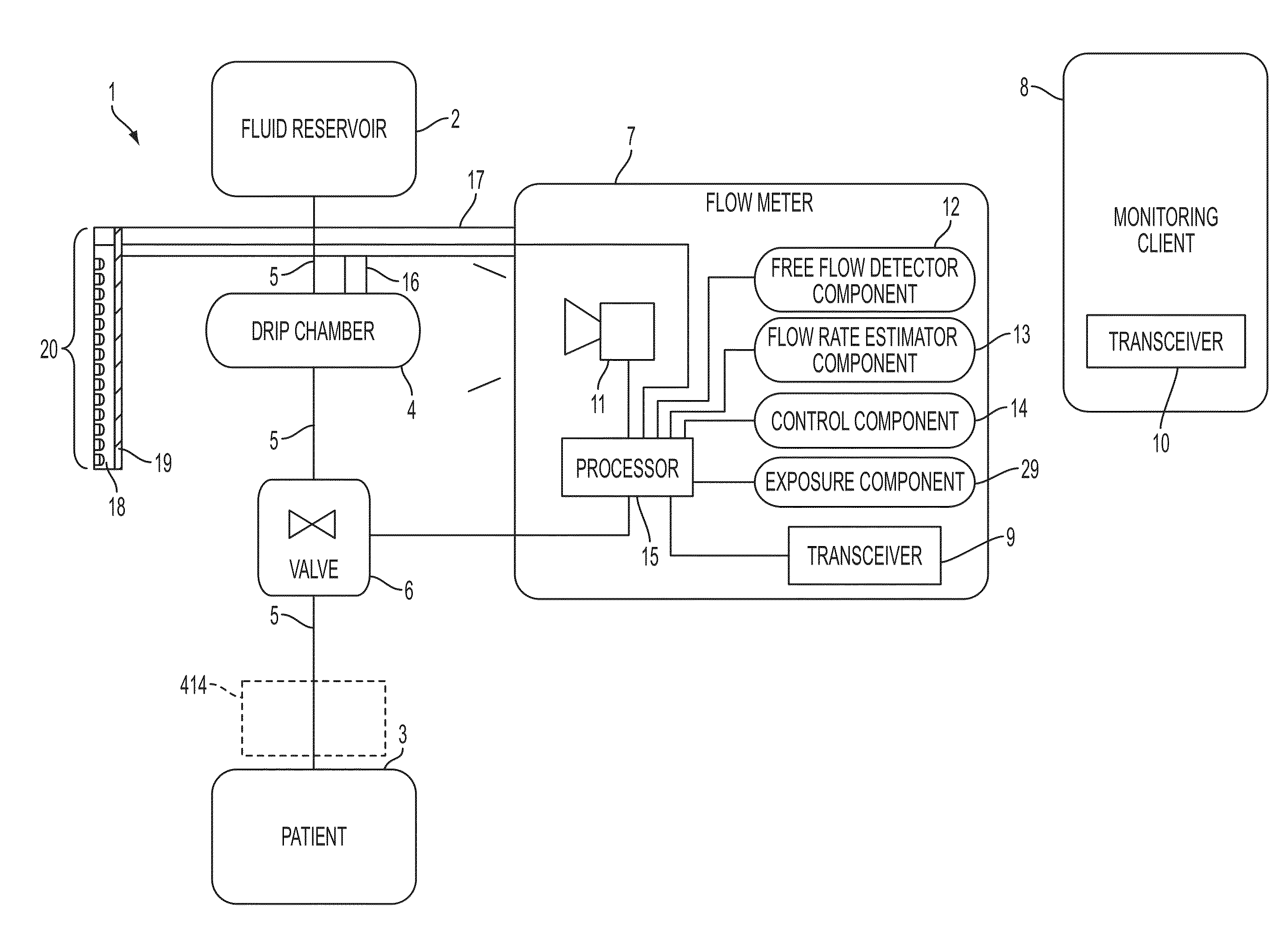
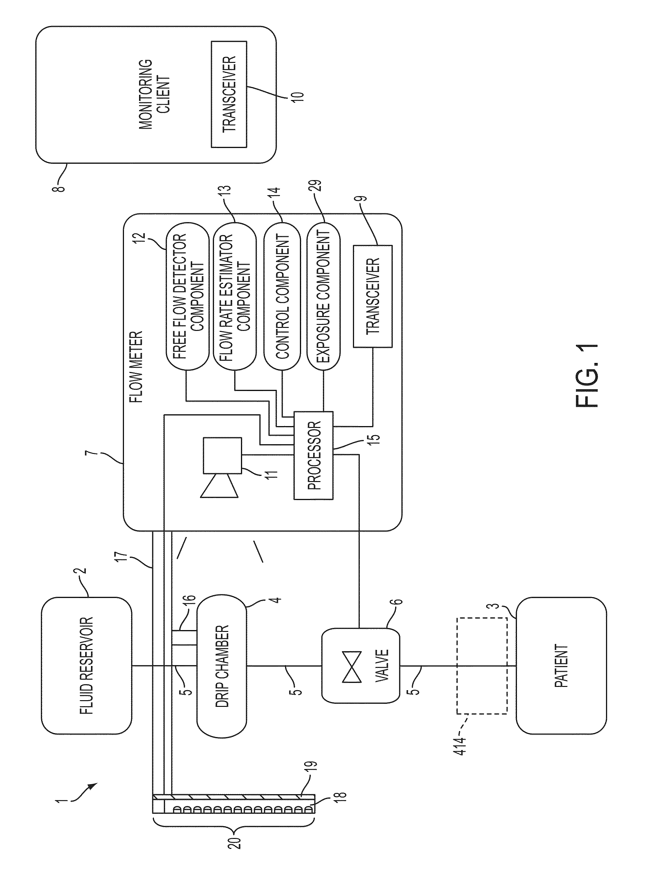
[0454]FIG. 1 shows a block diagram of a system 1 for regulating fluid flow in accordance with an embodiment of the present disclosure. For example, system 1 may regulate, monitor, and / or control the flow of fluid into a patient 3. The system 1 includes a fluid reservoir 2 for infusing fluid contained therein into the patient 3. The fluid reservoir 2 is gravity fed into a drip chamber 4 via a fluid tube 5. The fluid reservoir 2, the drip chamber 4, and the patient 3 may be considered as part of the system 1 or may be considered as separate or optional work pieces for the system 1 (e.g., any fluid reservoir 2 and drip chamber 4 may be used to treat any patient 3).

[0455]A flow meter 7 monitors the drip chamber 4 to estimate a flow rate of liquid flowing through the drip chamber 4. The fluid from the drip chamber 4 is gravity fed into a valve 6. The valve 6 regulates (i.e., varies) the flow of fluid from the fluid reservoir 2 to the patient 3 by regulating fluid flow from the drip chamb...


PUM


Abstract

A flow meter includes a first image sensor, a background pattern, and at least one processor. The first image sensor has a first field of view and is positioned to view a drip chamber within the first field of view. The background pattern is positioned within the field of view of the first image sensor, and the background pattern includes first and second portions. The processor is operatively coupled to the first image sensor and configured to: receive a first image from the first image sensor, and estimate at least one parameter of liquid within the drip chamber in accordance with a distortion of the background pattern caused by the liquid as indicated by the first image.

Description


Claims


Application Information

Patent Timeline
Owner DEKA PROD LLP
Why Eureka
Try Eureka