
System and method for spraying seeds dispensed from a twin row planter

a planter and twin row technology, applied in the direction of fertilising methods, liquid fertiliser regulation systems, agriculture, etc., can solve the problems of increasing material costs, excessive waste, and widening the gap between each planted seed

Active Publication Date: 2016-03-17
CAPSTAN
View PDF1 Cites 24 Cited by
  • Summary
  • Abstract
  • Description
  • Claims
  • Application Information

AI Technical Summary

Benefits of technology

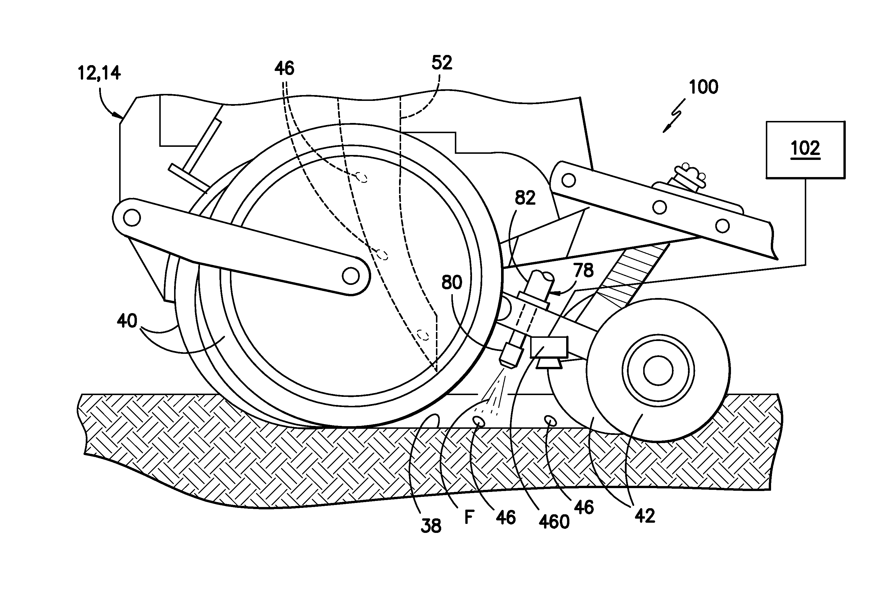
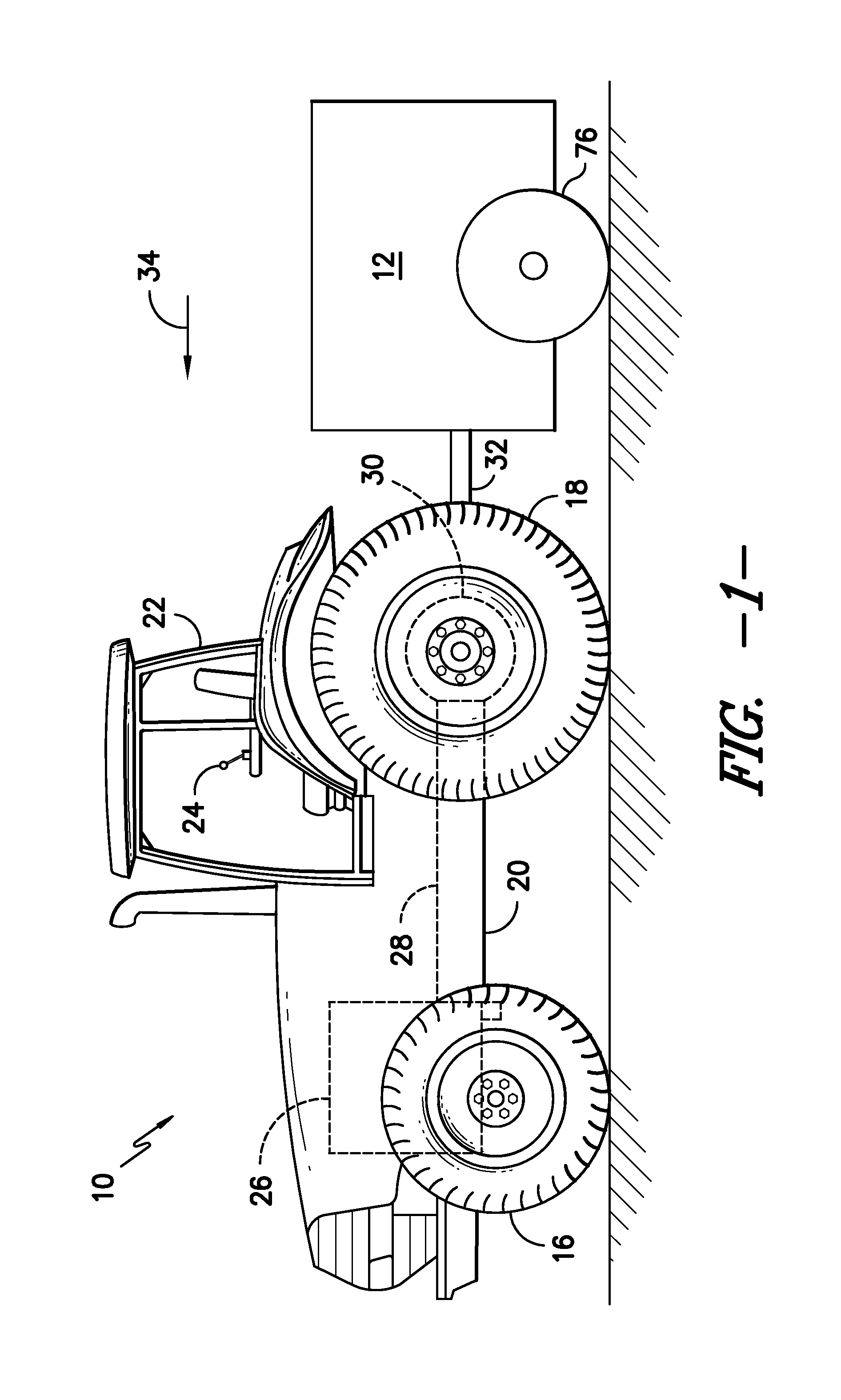
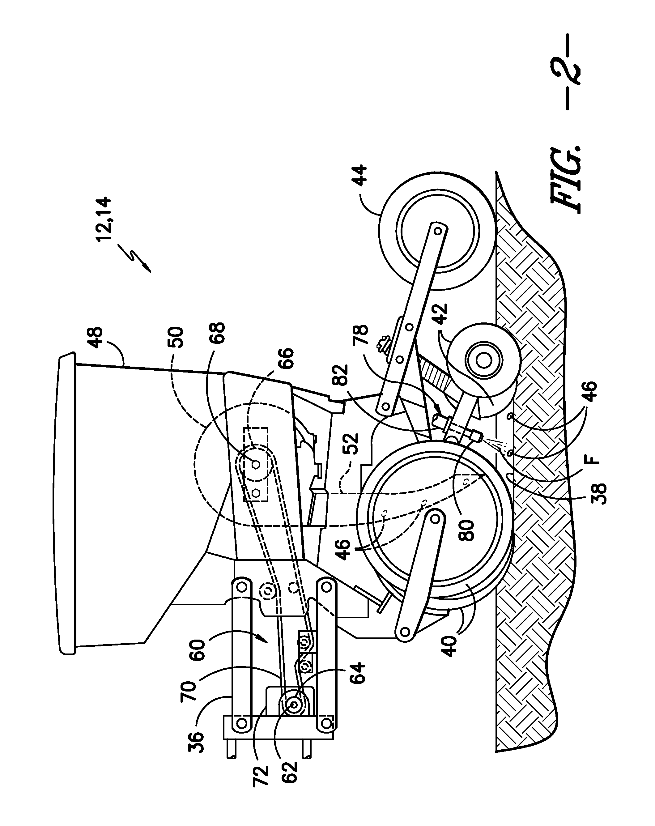
The present invention relates to a system and method for providing seed-specific placement of fluid as seeds are planted by a planter. The system includes a seed meter and a nozzle assembly with a valve. The seed meter dispenses seeds at a specific frequency and the nozzle assembly sprays fluid on or adjacent to each seed. The system uses a controller to determine the seed frequency based on a speed-related parameter of the planter, such as the rotational speed of the seed disc or the speed of a drive system component. The controller regulates the operation of the valve based on the seed frequency to ensure a metered amount of fluid is sprayed on or adjacent to each seed. The system may also include a sensor to measure the speed of the planter or the speed of a drive system component. The technical effects of the invention include improved seed placement, reduced fluid waste, and improved efficiency of the planter.

Problems solved by technology

Accordingly, a significant amount of fluid is sprayed in the areas located between the seeds, resulting in excessive waste and increased material costs.
However, to implement such narrow row spacings, the seed spacing along each row must be increased, thereby widening the gap between each planted seed.
As a result, the waste and material costs associated with the use of conventional spraying systems is even further increased.
However, such individual seed timing is very complex and data intensive, thereby requiring a controller with a significant amount of processor speed.

Method used


Image

  • System and method for spraying seeds dispensed from a twin row planter
  • System and method for spraying seeds dispensed from a twin row planter
  • System and method for spraying seeds dispensed from a twin row planter

Examples


Embodiment Construction

[0060]Reference now will be made in detail to embodiments of the invention, one or more examples of which are illustrated in the drawings. Each example is provided by way of explanation of the invention, not limitation of the invention. In fact, it will be apparent to those skilled in the art that various modifications and variations can be made in the present invention without departing from the scope or spirit of the invention. For instance, features illustrated or described as part of one embodiment can be used with another embodiment to yield a still further embodiment. Thus, it is intended that the present invention covers such modifications and variations as come within the scope of the appended claims and their equivalents.

[0061]In general, the present subject matter is directed to a system and method for providing seed-specific placement of a fluid as seeds are planted into a furrow by an agricultural planter. Specifically, in several embodiments, a controller may be configu...


PUM


Abstract

A system for providing seed-specific placement of fluid as seeds are planted by a twin row planter includes a planter row unit, at least one nozzle assembly, and a controller. The planter row unit includes a first seed meter configured to dispense seeds into a first furrow at a seed frequency and a second seed meter configured to dispense seeds into a second furrow at the seed frequency. The nozzle assembly is configured to spray the seeds dispensed into the first and second furrows, and includes a valve. The controller is communicatively coupled to the valve, and is configured to determine the seed frequency of the first and second seed meters based on a speed-related parameter of the planter. The controller is further configured to control operation of the valve based on the seed frequency such that fluid is sprayed at least one of on or adjacent to each seed.

Description

CROSS-REFERENCE TO RELATED APPLICATIONS[0001]This application is a divisional of U.S. patent application Ser. No. 13 / 869,537, filed on Apr. 24, 2013, which claims priority to U.S. Provisional Patent Application No. 61 / 684,964, filed on Aug. 20, 2012, the disclosures of which are hereby incorporated by reference in their entirety for all purposes.FIELD OF THE INVENTION[0002]The present subject matter relates generally to a system and method for spraying seeds and, more particularly, to a system and method for providing seed-specific placement of a fluid as seeds are planted within a furrow by an agricultural planterBACKGROUND OF THE INVENTION[0003]In the agricultural industry, plants and plant precursors (e.g., seeds) are often sprayed with an agricultural fluid at the time of planting in order to enhance germination and early development. For example, when planting certain crops, it is often desirable to spray fertilizers, pesticides, insecticides, fungicides and / or various other ag...

Claims


Application Information

Patent Timeline
Patent Type & Authority Applications(United States)
IPC IPC(8): A01C7/06A01C7/12A01C21/00A01C23/00
CPCA01C7/06A01C23/007A01C21/00A01C7/128A01C1/06A01C7/105
Inventor GRIMM, JEFFREY JOHNKOLB, TROY C.
Owner CAPSTAN
Learn More