Mobile terminal
a mobile terminal and terminal technology, applied in the field of mobile terminals, can solve the problem of receiving attention as a wearable device, and achieve the effect of improving user convenien
- Summary
- Abstract
- Description
- Claims
- Application Information
AI Technical Summary
Benefits of technology
Problems solved by technology
Method used
Image
Examples
first embodiment
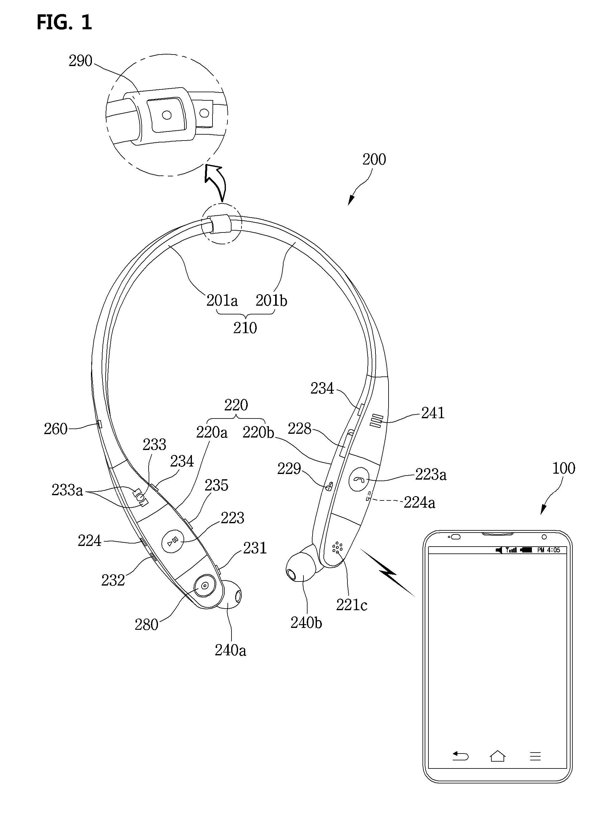
[0214]Referring to FIGS. 7 and 8, the wearable device 200 according to this embodiment has a configuration that is mostly identical to that of the wearable device 200 but there is a difference in a structure in which the front camera module 280 is mounted at each of a left body part and a right body part and is tilted toward the front.
[0215]In more detail, the front part (or upper part) of the front camera module 280, that is, a lens part, substantially may form the same plane as the front part (or upper part) of the body part 220 and may be tilted toward the front at a predetermined angle by a user's manipulation.
[0216]In more detail, when a user wears the wearable device 200 on the neck, the body part 220 is placed on the user's collar bone and chest. At this state, when the front camera module 280 is turned on for capturing, a subject that a user wants to capture does not come into the camera lens. In addition, when a user can manually manipulate the front camera module 280 or i...
third embodiment
[0217]FIG. 9 is an exploded perspective view illustrating a tilting mechanism of a front camera module equipped at a wearable device according to the present invention. Referring to FIG. 9, looking at a tilting structure of a front camera module according to an embodiment of the present invention, a camera hole 221b of a long hole form where the front camera module 280 is received is formed at the center part of the upper part housing 221 configuring the body part 220. A tilting member 271 is slidably mounted at the rear of the camera hole 221b. When the front camera module 280 is in a state before tilting, the tilting member 271 surrounds the rear side part of the front camera module 280 to prevent it from shaking. Then, the front end part of the camera module 221b is formed to be rounded in a form of surrounding the front side part of the front camera module 280.
[0218]In more detail, the tilting member 271 includes a cover part 271b bent in a form of “┐” to cover the rear portion ...
sixth embodiment
[0266]In brief, the feature of the wearable device 200 is that the detachable front camera module 280 may be detachably coupled to the top surface in addition to the front end part of the body part 220. However, when the front camera module 280 is coupled to the top surface of the body part 220, in order to obtain a viewing angle, an angle formed by the connection part 285 and the insertion part 286 may need to be changed.
[0267]As another method, it is possible to obtain a sufficient viewing angle by adjusting a rotation angle range of the camera 282. For example, when a separation distance between the rear of the camera 282 and the connection part 285 is adjusted, a rotation angle range of the camera 282, that is, a widen angle of a parabolic trajectory, may be adjusted. Then, a rotation range of the camera 282 may become greater or less.
[0268]FIGS. 19 and 20 are perspective views of a wearable device according to a seventh embodiment of the present invention. Referring to FIGS. 1...
PUM
 Abstract
Description
Claims
Application Information
 - R&D
- Intellectual Property
- Life Sciences
- Materials
- Tech Scout
- Unparalleled Data Quality
- Higher Quality Content
- 60% Fewer Hallucinations
Browse by: Latest US Patents, China's latest patents, Technical Efficacy Thesaurus, Application Domain, Technology Topic, Popular Technical Reports.
© 2025 PatSnap. All rights reserved.Legal|Privacy policy|Modern Slavery Act Transparency Statement|Sitemap|About US| Contact US: help@patsnap.com


