Insufflation apparatus

Inactive Publication Date: 2016-04-21
OLYMPUS CORP
View PDF6 Cites 177 Cited by
  • Summary
  • Abstract
  • Description
  • Claims
  • Application Information

AI Technical Summary

Benefits of technology

[0008]An insufflation apparatus according to an aspect of the present invention includes: a gas-feeding-source connecting section connected to a gas feeding source that feeds a predetermined gas; a gas-feeding-conduit connecting section for connecting a gas feeding conduit that feeds the predetermined gas to a subject; a first conduit that connects the gas-feeding-source connecting section and the gas-feeding-conduit connecting section; a suction-conduit connecting section for connecting a suction conduit that sucks the predetermined gas from an inside of the subject; a pump for circulating the predetermined gas to the subject; a conduit for circulation that connects the suction-conduit connecting section and the pump; a connection conduit that connects the pump and the first conduit; a suction-source connecting section connected to a suction source for sucking the predetermined gas; a second conduit that connects the suction-source connecting section and the conduit for circulation; a switching unit that selectively switches a state in which the predetermined gas sucked from the suction-conduit connecti

Problems solved by technology

However, since pressure of the gas in the abdominal cavity drops because of the suction, it is necessary to feed new carbon dioxide f

Method used


Image

  • Insufflation apparatus
  • Insufflation apparatus
  • Insufflation apparatus

Examples


first embodiment

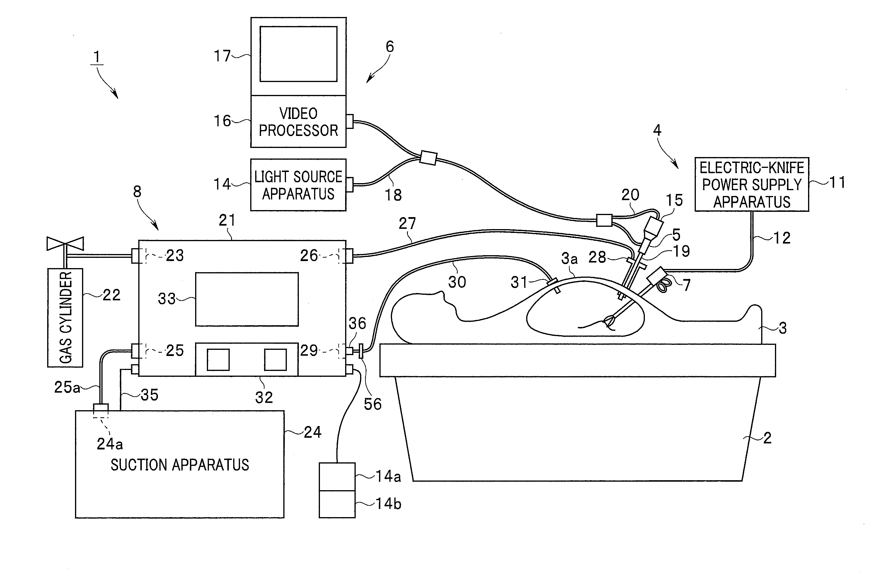
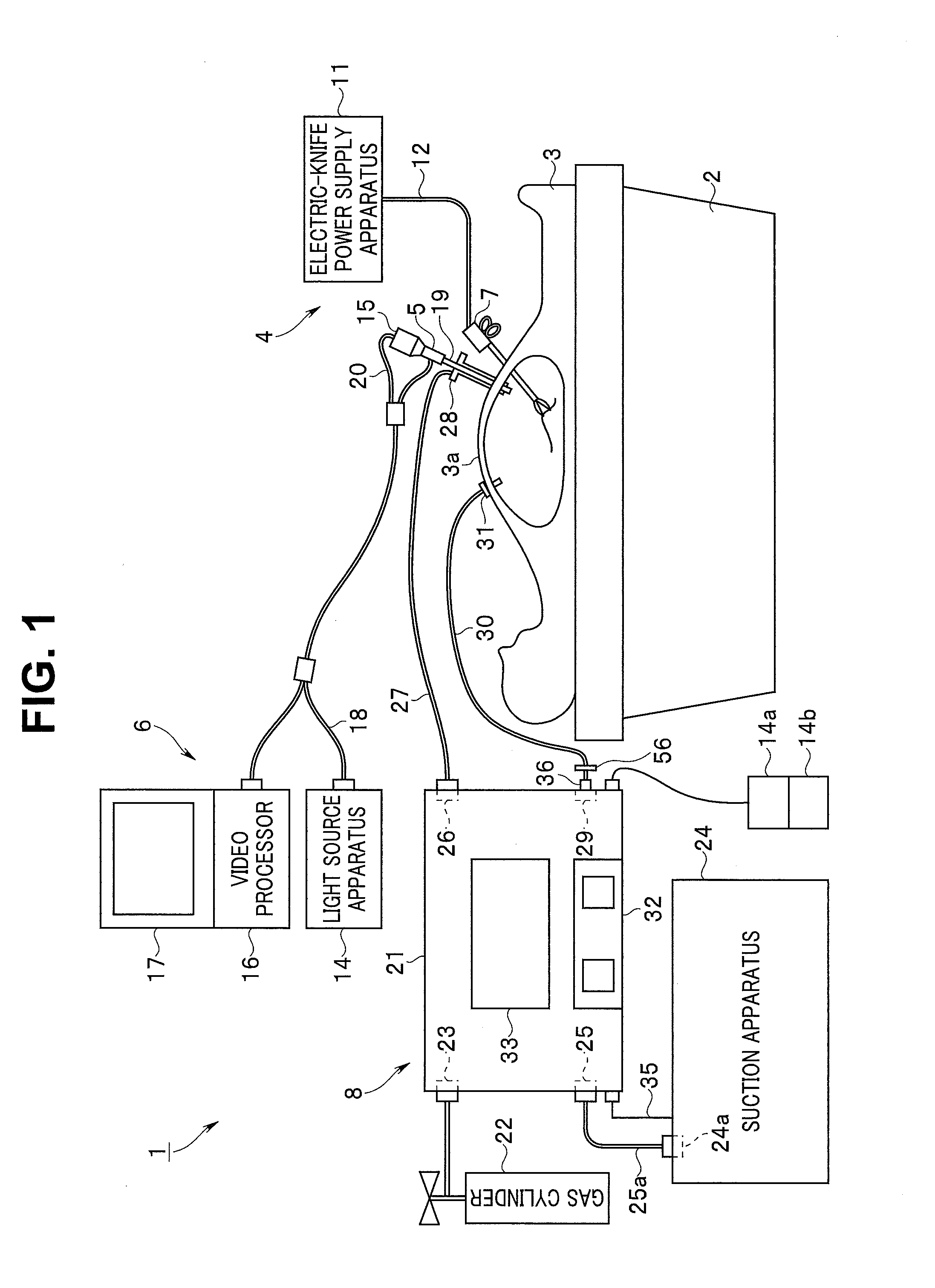
[0036]As shown in FIG. 1, an endoscope operation system 1 includes an electric knife apparatus 4 functioning as a surgical apparatus for performing an operation on a patient 3 treated as a subject placed on a bed 2, an endoscope apparatus 6 for observing a surgical operation using an endoscope 5, and an insufflation apparatus 8 in a first embodiment that performs insufflation in an abdomen 3a set as an operation target in order to secure a visual field by the endoscope 5 and a region to be operated by an electric knife 7. Note that the abdomen 3a may be defined to form the subject.

[0037]The electric knife apparatus 4 is configured by an electric-knife power supply apparatus 11 that generates high-frequency power and the electric knife 7 to which the high-frequency power generated by the electric-knife power supply apparatus 11 is supplied via a cable 12. A surgeon can feed a high-frequency current to a diseased part grasped by, for example, a bipolar electrode at a distal end of the...

second embodiment

[0122]A second embodiment of the present invention is explained. FIG. 11 shows an insufflation apparatus 8E in a second embodiment of the present invention. The insufflation apparatus 8E includes the apparatus main body 21 in which the check valve 74 explained in FIG. 9 is used instead of the third electromagnetic valve 53 in the insufflation apparatus 8A shown in FIG. 2B. In the present embodiment, the insufflation apparatus 8E includes means for detecting deterioration in a filter characteristic of a filter 56E without using the characteristic detection circuit 63 shown in FIG. 2B.

[0123]FIG. 12 shows a structure near the suction cap receiver 29 in the present embodiment. FIG. 12(A) shows the structure near the suction cap receiver 29. FIG. 12(B) shows the filter 56E fit in the recess of the suction cap receiver 29 and detachably mounted.

[0124]In the first modification of the first embodiment, the suction cap receiver 29 is configured to include the recess of the two-stage structur...


PUM


Abstract

An insufflation apparatus includes a gas-feeding-conduit connecting section for connecting a conduit that feeds a predetermined gas to a subject, a first conduit that connects a gas-feeding-source connecting section and the gas-feeding-conduit connecting section, a suction-conduit connecting section for connecting a conduit that sucks the predetermined gas from an inside of the subject, a pump for circulating the predetermined gas to the subject, a conduit for circulation that connects the suction-conduit connecting section and the pump, a second conduit that connects a suction-source connecting section and the conduit for circulation, and a control section that controls a switching unit to operate in a circulation operation mode for circulating the predetermined gas to the subject via the pump and a suction operation mode for sucking the predetermined gas to the suction source side via the second conduit.

Description

CROSS REFERENCE TO RELATED APPLICATION[0001]This application is a continuation application of PCT / JP2014 / 064938 filed on Jun. 5, 2014 and claims benefit of Japanese Application No. 2013-163551 filed in Japan on Aug. 6, 2013, the entire contents of which are incorporated herein by this reference.BACKGROUND OF THE INVENTION[0002]1. Field of the Invention[0003]The present invention relates to an insufflation apparatus that performs insufflation in a body cavity.[0004]2. Description of the Related Art[0005]In recent years, a surgical operation under an observation by a laparoscope has been widely adopted. In such a surgical operation by the laparoscope, an insufflation apparatus is used in order to feed a predetermined gas such as carbon dioxide into an abdominal cavity and secure an observation visual field by the laparoscope and a region in performing an operation.[0006]When treatment is performed using an electric knife, for a case in which smoke or the like occurs in the abdominal c...

Claims


Application Information

Patent Timeline
IPC IPC(8): A61M13/00
CPCA61M13/006A61M2202/0225A61M2205/75A61B1/015A61B1/3132A61M2205/3334A61M2205/3344A61M2210/1017A61M2202/0007
Inventor HIRAGA, KUNITOSHIFURUKAWA, NOBUYUKI
Owner OLYMPUS CORP
Why Eureka
Try Eureka