Calibration of imagers with dynamic beam shapers

a beam shaper and imager technology, applied in the field of imager calibration, can solve the problems of cumbersome calibration procedures for imagers with such (highly) adaptable beam shapers, and achieve the effect of reducing the number of imagers

Active Publication Date: 2016-04-28
KONINKLJIJKE PHILIPS NV
View PDF4 Cites 21 Cited by
  • Summary
  • Abstract
  • Description
  • Claims
  • Application Information

AI Technical Summary

Benefits of technology

[0033]“(pre-)Filter/beam shaper” as used herein is a pre-filter that operates to pre-attenuate the x-ray beam supplied by the radiation source before the x-ray beam is incident on the object/detector. The primary goal of the pre-filter is to modulate intensity of the beam although there are also changes in the spectrum and of the mean energy of the beam. Preferably, the filter can be operated so that individually addressable filter elements can be spatially re-arranged or otherwise activated to effect a plurality of different energy intensity profiles in the beam that are ta

Problems solved by technology

However it has turned out that calibration procedures (that is, the acquisition of gain correction ima

Method used


Image

  • Calibration of imagers with dynamic beam shapers
  • Calibration of imagers with dynamic beam shapers
  • Calibration of imagers with dynamic beam shapers

Examples


Embodiment Construction

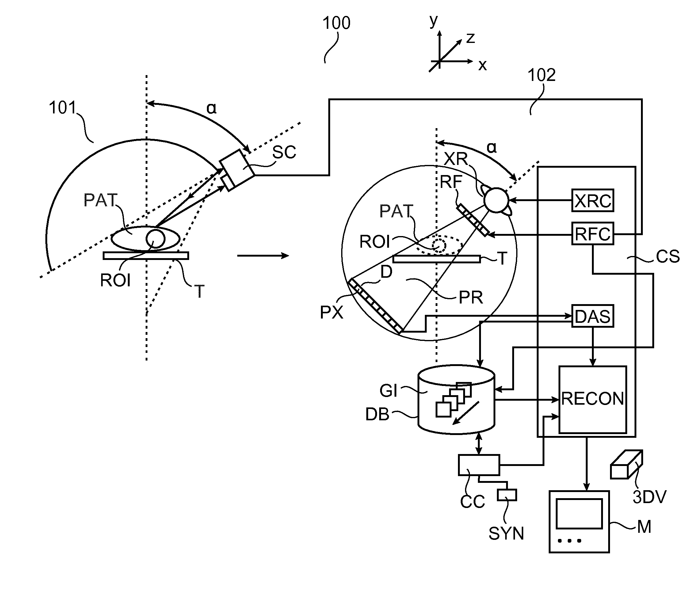
[0042]FIG. 1 shows an imaging arrangement according to one embodiment. The arrangement 100 includes an internal imaging system 102 based on ionizing radiation and an object shape detector arrangement 101 whose operation is based on non-ionizing radiation.

[0043]The internal imager allows non-intrusively imaging the internals of an object PAT at a region of interest ROI whereas shape detector allows detecting the outer shape or silhouette of the either the whole object PAT or at least of the ROI.

[0044]In one embodiment, the imaging system 102 is a 3-D CT imager of the energy integrating or photon counting spectral type. In other, simpler embodiments, the imaging system 102 is envisaged as an interventional 2-D x-ray imager, in particular of the C-arm type.

[0045]When the imaging system 102 is a CT imager, its basic components include a frame (not shown) comprising a rigid, stationery gantry (not shown) and arranged therein a movable, in particular rotatable, (relative to the stationary...


PUM


Abstract

Calibration methods and related calibration controllers (CC) for calibrating imaging apparatuses (102) such as a 3D computed tomography imager or a 2D x-ray imager. The imaging apparatuses (102) are equipped with a dynamic beam shaper (RF). The dynamic beam shaper (RF) allows adapting the energy profile of a radiation beam (PR) used in the imaging apparatuses (102) to a shape of an object (PAT) to be imaged. A plurality of gain images are acquired in dependence on a shape of the object and the view along which the gain images are acquired or a target gain image is synthesized from a plurality of basis gain images (BGI).

Description

FIELD OF THE INVENTION[0001]The present invention relates to calibration methods, to imagers, to calibration controllers, to imaging systems, to a computer program element, and to a computer readable medium.BACKGROUND OF THE INVENTION[0002]Most of today's CT (computed tomography) scanners use beam shapers, often called bowtie filters, to adapt the intensity profile of the scanner's x-ray (that is incident on a patient) to the thickness profile of the patient to be imaged. The so adapted, in general spatially non-uniform, x-ray profile helps secure a number of advantages: less patient dose, less x-ray scatter, more homogeneous image quality, and reduction of the dynamic range requirements for the scanner's detector by using lower intensity in certain parts of the beam, especially in those parts in direct irradiation areas. Some beam shapers allow selection from a (usually very limited) set of available filter bodies that are based on a rough patient classification (e.g. child, adult,...

Claims


Application Information

Patent Timeline
IPC IPC(8): A61B6/00A61B6/03
CPCA61B6/585A61B6/544A61B6/4035A61B6/032A61B6/03A61B6/5205A61B6/5258A61B6/582A61B6/4441A61B6/42A61B6/545
Inventor HERRMANN, CHRISTOPHMENSER, BERND
Owner KONINKLJIJKE PHILIPS NV
Why Eureka
Try Eureka