Optical position detection of a timepiece crown stem

Active Publication Date: 2016-04-28
THE SWATCH GRP RES & DEVELONMENT LTD
View PDF4 Cites 64 Cited by
  • Summary
  • Abstract
  • Description
  • Claims
  • Application Information

AI Technical Summary

Benefits of technology

[0007]The proposed new solution has the advantage that relative movements can be detected very precisely. For instance, a relative angular position detection resolution of about 9600 positions per full rotation of the crown may be achieved with the present solution, which is by far more than what can be currently achieved with

Problems solved by technology

Furthermore, the proposed arrangement takes up little space, which i

Method used


Image

  • Optical position detection of a timepiece crown stem
  • Optical position detection of a timepiece crown stem

Examples


Embodiment Construction

[0014]An embodiment of the present invention will now be described in detail, with reference to the attached figures. Identical or corresponding functional and structural elements which appear in the different drawings are assigned the same reference numerals.

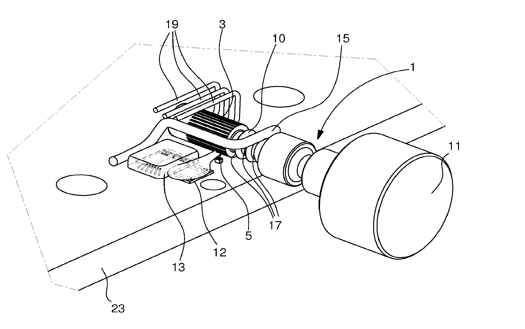
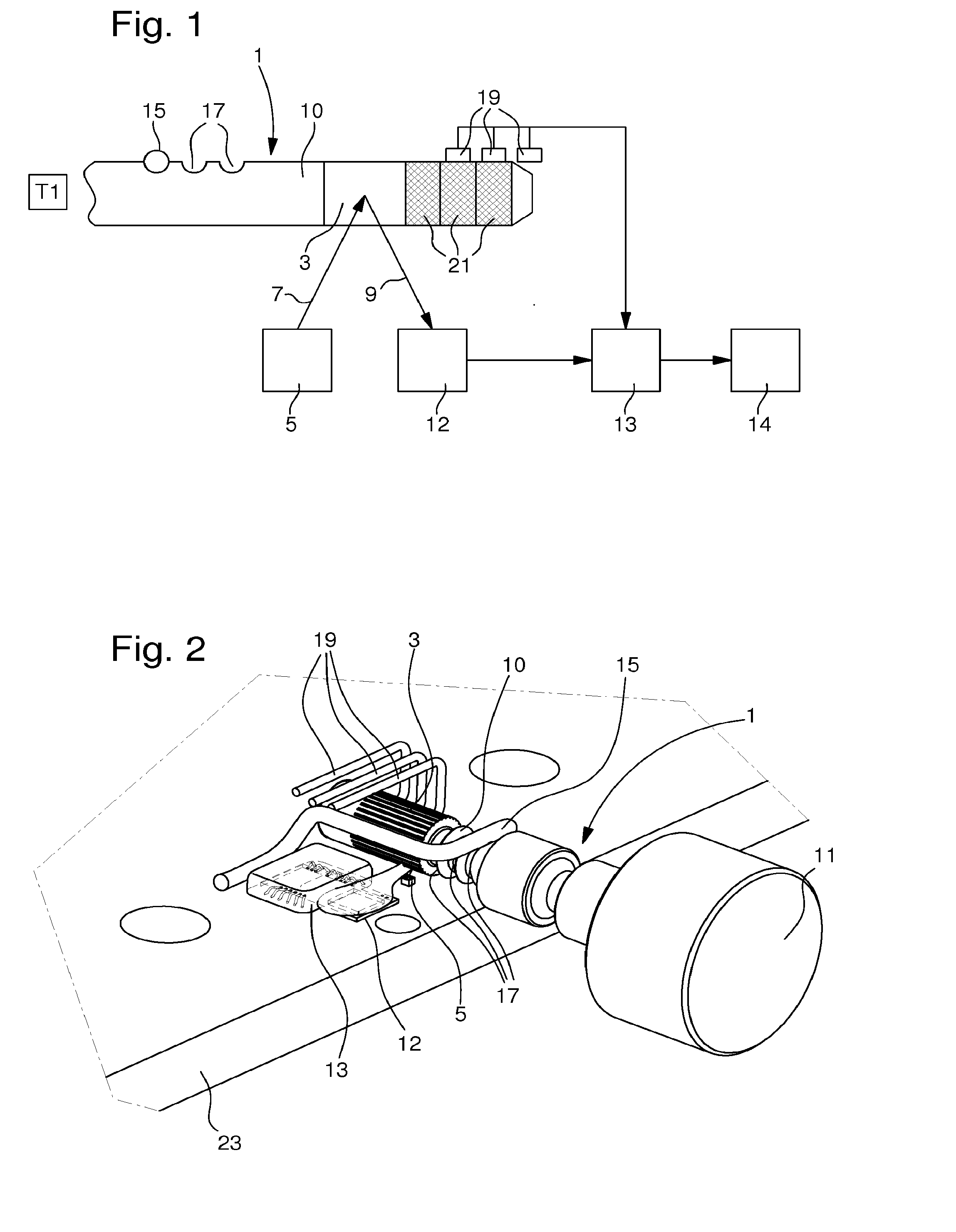
[0015]FIG. 1 shows in a simplified manner a block diagram of the arrangement that is used to detect a position of a rotational device, such as a setting stem 1 of an electronic watch. FIG. 2 shows a perspective view of a structure that can be applied for such a functional arrangement. Illustrated in FIGS. 1 and 2 is the shaft 10 of the setting stem. When applied to a wristwatch, the diameter of the shaft is typically in the range of 0.5 to 2 mm. One end of this shaft 10, in this example the left end, may have for instance a crown or knob that a user can use to push, pull or rotate the shaft 10. The shaft 10 has on its surface a reflection area 3. This reflection area may simply be a non-perfect shaft surface having imperfection...


PUM


Abstract

A method of detecting a movement of a timepiece setting stem arranged to be moved axially along and/or rotated about its longitudinal axis. The method includes a light source illuminating a portion of the setting stem; a light detector receiving a reflected or diffracted light pattern from the setting stem; a processor forming a first pixel pattern representative of the reflected light pattern at a first time instant; the processor forming a second pixel pattern representative of the reflected light pattern at a second, later time instant; and determining that the setting stem has been moved, if the second pixel pattern is different or shifted with respect to the first pixel pattern.

Description

[0001]This application claims priority from European Patent Application No. 14190708.9 filed Oct. 28, 2014, the entire disclosure of which is incorporated herein by reference.TECHNICAL FIELD[0002]The invention relates to the field of movement or position detection of a timepiece crown stem. More specifically, the present invention relates to a method of optically detecting a movement of a timepiece setting stem. The invention also relates to a corresponding sensor arrangement.BACKGROUND OF THE INVENTION[0003]Generally, incremental or absolute encoding schemes can be used to measure the angular position of a rotating device, such as a volume-control knob or the crown of an electronic watch. In many applications, such rotating control elements are also axially displaceable in order to trigger or activate various functions of a device. Therefore, it may also be necessary to measure the axial position of the same knob or crown. In watch applications, the axial position of setting stem, ...

Claims


Application Information

Patent Timeline
IPC IPC(8): G01D5/30G04B27/00G01D5/252
CPCG01D5/30G04B27/002G01D5/252G04C3/001G01D5/347
Inventor FERRI, YVANBALMER, RAPHAELSCHMUTZ, DAMIENLAGORGETTE, PASCAL
Owner THE SWATCH GRP RES & DEVELONMENT LTD
Why Eureka
Try Eureka