Vehicle lighting unit

Active Publication Date: 2016-04-28
STANLEY ELECTRIC CO LTD
View PDF4 Cites 20 Cited by
  • Summary
  • Abstract
  • Description
  • Claims
  • Application Information

AI Technical Summary

Benefits of technology

[0015]With this configuration, even when two types of LEDS each having a different amount of light rays are used, th

Problems solved by technology

However, since the vehicle lighting unit described in Japanese Patent Application Laid-Open No. 2012-248358 utilized such a light guiding plate, which may adversely provide a wider emission area.
Accordingly, it is difficul

Method used


Image

  • Vehicle lighting unit
  • Vehicle lighting unit
  • Vehicle lighting unit

Examples


Embodiment Construction

[0024]A description will now be made below to vehicle lighting units of the presently disclosed subject matter with reference to the accompanying drawings in accordance with exemplary embodiments.

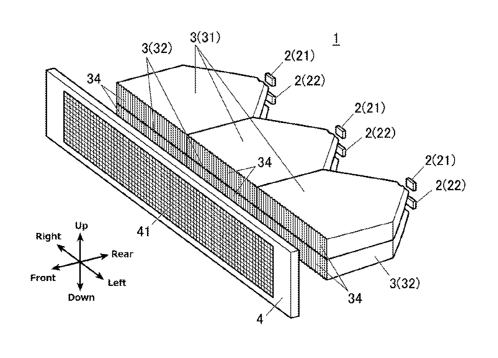
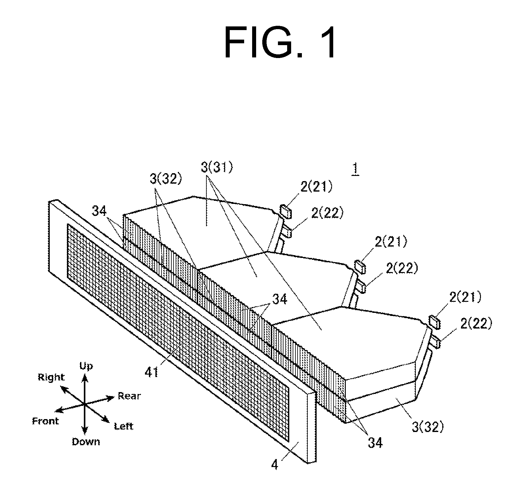
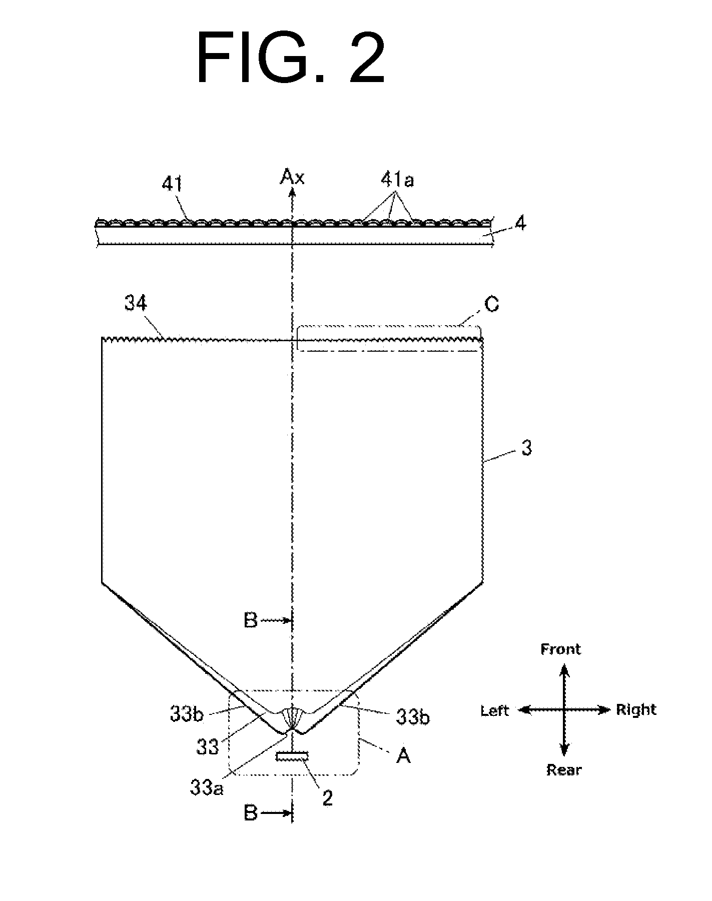
[0025]FIG. 1 is a perspective view of essential parts of a vehicle lighting unit 1 made in accordance with the principles of the presently disclosed subject matter. FIG. 2 is a plan view of parts corresponding to each LED in the vehicle lighting unit 1. FIGS. 3A, 3B, and 3C are an enlarged view of part A in FIG. 2; a cross-sectional view taken along line B-B in FIG. 2; and an enlarged view of part C in FIG. 2, respectively. Furthermore, FIGS. 4A and 4B are each a plan view illustrating the manner in which the light rays are refracted at a light incident face 33 of a light guiding lens 3.

[0026]Note that the directions used herein are defined so that the direction in which light rays travel is the front direction (to the front side, forward), and the flat plate shape of the light guiding lens...


PUM


Abstract

A vehicle lighting unit can include a first LED and a second LED each having a different color; a first light guiding lens and a second light guiding lens disposed in front of the first and second LEDs, respectively, configured to guide light rays from the first and second LED, respectively, to cause the light rays to exit therethrough forward; and a diffusion lens disposed in front of the first and second light guiding lenses, configured to diffuse the light rays from the first and second light guiding lenses. The light exiting faces of the first and second light guiding lenses can be configured to be long and adjacent to each other in the vertical direction with the lengthwise directions coincide with each other. The diffusion lens can have a long shape so as to cover the entire front light exiting faces of the first and second light guiding lenses.

Description

[0001]This application claims the priority benefit under 35 U.S.C. §119 of Japanese Patent Application No. 2014-216968 filed on Oct. 24, 2014, which is hereby incorporated in its entirety by reference.TECHNICAL FIELD[0002]The presently disclosed subject matter relates to vehicle lighting units to be installed on a vehicle body, and in particular, a vehicle lighting unit capable of emitting light rays with a plurality of colors from a single light emitting part.BACKGROUND ART[0003]Some conventionally known vehicle lighting units to be installed on a vehicle body can include those capable of emitting light rays with a plurality of colors from a single light emitting part so as to function as a plurality of types of lamp.[0004]Japanese Patent Application Laid-Open No. 2012-248358 discloses this type of vehicle lighting unit, in which a first light source is allowed to face to one side end face of a light guiding plate while a second light source is allowed to face to the other side end...

Claims


Application Information

Patent Timeline
IPC IPC(8): F21V8/00F21S8/10
CPCG02B6/0068G02B6/0076G02B6/0078F21Y2101/02G02B6/0051F21S48/00F21Y2113/005G02B6/0073B60Q1/0041B60Q1/0052B60Q1/0058F21Y2115/10F21Y2113/13B60Q1/38B60Q2400/20B60Q2400/30G02B6/002G02B6/0046F21S43/249F21S43/243F21S43/239F21S43/14F21S43/15F21S43/26
Inventor SATO
Owner STANLEY ELECTRIC CO LTD
Why Eureka
Try Eureka