Immersion nozzle

a technology of immersion nozzle and nozzle head, which is applied in the direction of melt-holding vessels, casting apparatus, manufacturing tools, etc., can solve the problems of defective slab quality, increased risk of nozzle disorder, and increased risk of nozzle discharge flow, so as to reduce the entrainment of mold powder, suppress the flow of in-mold bath surface, and promote the floating of in-molten steel inclusions.

Pending Publication Date: 2022-05-05
KROSAKI HARIMA CORP
View PDF0 Cites 0 Cited by
  • Summary
  • Abstract
  • Description
  • Claims
  • Application Information

AI Technical Summary

Benefits of technology

[0030]The flat immersion nozzle of the present invention can control a molten steel flow to gradually increase / reduce the flow rate thereof in a continuous manner, without fixedly or completely separating the direction of the molten steel flow over the range from a central region to a lateral region inside the immersion nozzle, thereby ensuring an appropriate balance of molten steel flows within the immersion nozzle. Thus, even in continuous casting carried out under casting conditions, particularly, a condition of a molten steel flow rate of about 0.04 (t / (min·cm2)) or more, as measured with reference to the position of minimum cross-sectional area in a region around an upper end of the immersion nozzle where a transverse cross-section of the inner bore is a circular shape, wherein the continuous casting tends to cause a situation where a high-speed or high-volume molten steel flow is generated on the side of each of the lateral discharge ports, it becomes possible to appropriately suppress the flow velocity or flow rate of molten steel discharged from the discharge ports to stabilize the in-mold bath surface or the like, i.e., reduce the fluctuation of the in-mold bath surface or the like.
[0031]Then, since the fluctuation of the in-mold bath surface is suppressed, it becomes possible to reduce entrainment of a mold powder or the like into the mold, and promote floating of in-molten steel inclusions, thereby improving quality of slabs. Further, since an excessive molten steel flow toward lateral walls of the mold is suppressed, it becomes possible to reduce a risk of the occurrence of accident such as breakout.

Problems solved by technology

However, when the inner bore has a region where it is increased in terms of width, and flattened, the flow of molten steel inside the immersion nozzle becomes more likely to be disordered, and thus a discharge flow toward the mold also becomes more likely to be disordered.
Resulting turbulence of the molten steel flow becomes a factor causing defective quality of slabs, an increase in danger during casting operation, etc., such as an increase in fluctuation of the surface of (molten steel) bath in the mold (in-mold bath surface), entrainment of a mold powder into a slab, or unevenness in temperature.
However, the means to divide the molten steel flow in a right-left direction is still likely to cause a situation where the fluctuation of the molten steel discharge flow between right and left discharge ports is increased, and thereby the fluctuation of the in-mold bath surface is increased.

Method used


Image

  • Immersion nozzle
  • Immersion nozzle
  • Immersion nozzle

Examples


example a

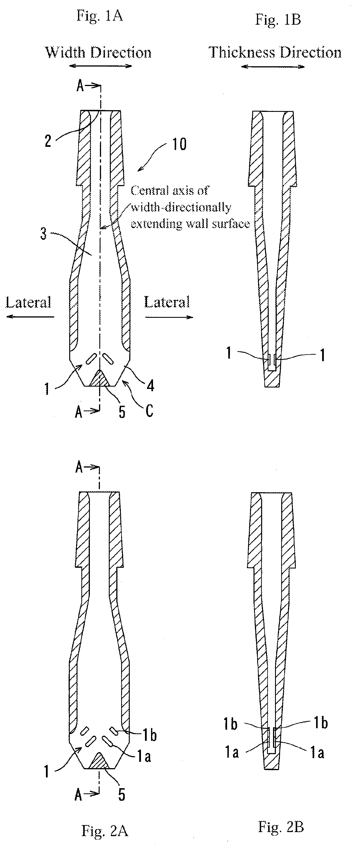
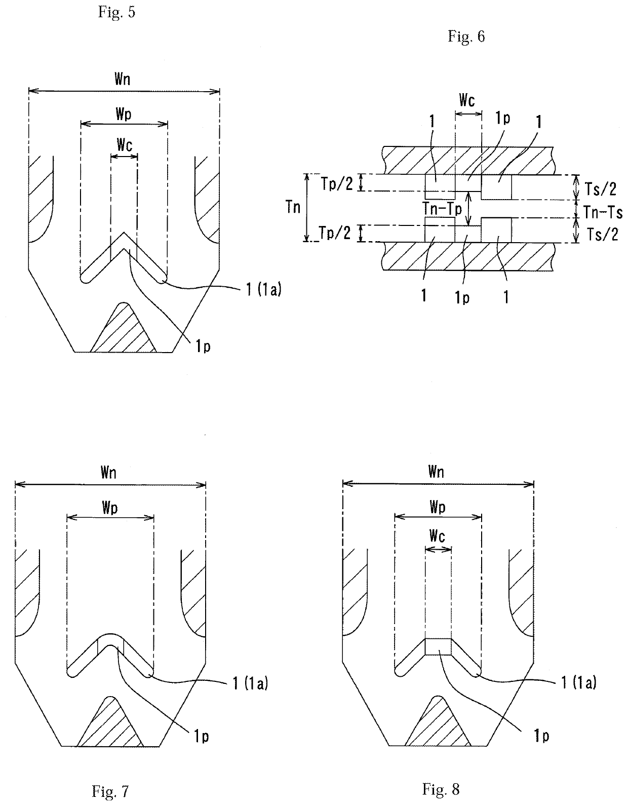
[0070]Example A is a result of water model experiments, showing a relationship between the ratio Ts / Tn or Tp / Tn of the protrusion length Ts of the opposed lower lateral protrusions 1a toward a space of the inner bore of the immersion nozzle or the protrusion length Tp of the opposed central protrusions 1p toward the space of the space of the inner bore (the total length of the plane-symmetrical protrusions) to the thickness (length in the short-side direction) Tn of the inner bore of the immersion nozzle, and a degree of fluctuation of the in-mold bath surface (in-mold uneven flow index, in-mold bath surface fluctuation height), with respect to each immersion nozzle according to the second embodiment of the present invention illustrated in FIG. 2, which is provided with the two-stage axial symmetrical and plane-symmetrical lateral protrusions 1a, 1b wherein the central protrusion 1p is not provided between each of the two pairs of lower lateral protrusions 1a, and according to the f...

example b

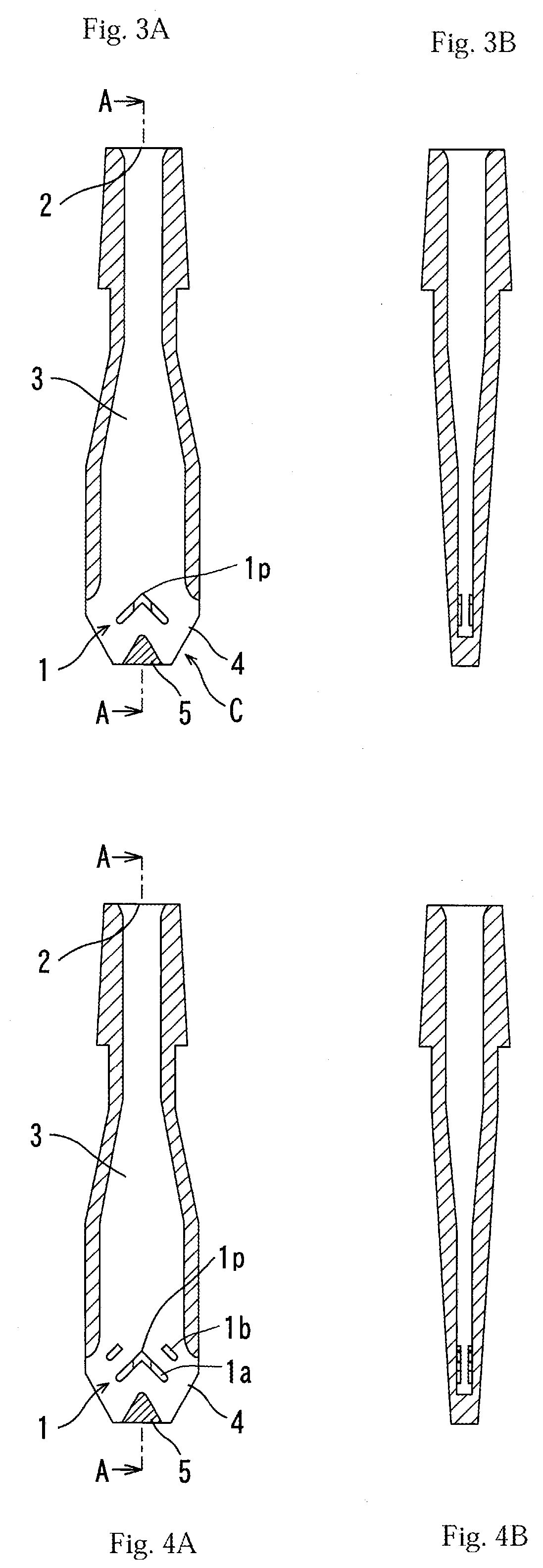
[0104]Example B is a result of water model experiments, showing a degree of in-mole bath surface fluctuation when the upper end surface of each of the lower lateral protrusion 1a and the central protrusion 1p is formed in a planar shape extending obliquely downwardly toward the center of the inner bore, as shown in FIG. 9, in the forth embodiment of the present invention illustrated in FIG. 4.

[0105]Here, the ratio Ts / Tn regarding the lower lateral protrusions and the ratio Tp / Tn regarding the central protrusions were set, respectively, to 0.74 and 0.18, and two cases where the inclination angle (θ in FIG. 9) of each of the lower lateral protrusion and the central protrusion toward the center of the inner bore was set to 0 degree (horizontal) and 45 degrees were compared with each other. The remaining conditions are the same as those of Example A.

[0106]A result is shown in FIG. 19. The vertical axis of FIG. 19 represents an average value of maximum bath surface fluctuation values Sw ...


PUM

PropertyMeasurementUnit
heightaaaaaaaaaa
thickness Tnaaaaaaaaaa
width Wnaaaaaaaaaa

Abstract

It is intended to provide a flat immersion nozzle capable of stabilizing a molten steel discharge flow to stabilize an in-mold bath surface, i.e., reduce the fluctuation of the in-mold bath surface. Provided is an immersion nozzle having a flat portion whose inner bore has a thickness and a width greater than the thickness, wherein two lateral protrusions each protruding in a thickness direction are provided on each of opposed walls of the flat portion extending in a width direction. The lateral protrusions are arranged at axial symmetrical positions with respect to a longitudinal central axis of the width-directionally extending walls, in pairs, such that each of them extends obliquely downwardly in the width direction, wherein two pairs of the lateral protrusions are arranged, respectively, on the opposed width-directionally extending walls, in opposed relation.

Description

TECHNICAL FIELD[0001]The present invention relates to an immersion nozzle for use in continuous casting to pour molten steel from tundish into a mold, and more particularly to an immersion nozzle, such as those used for continuous casting of a thin slab, a medium-thick slab or the like, which is flat in terms of transverse cross-section (cross-section in a direction perpendicular to a vertical direction) near a discharge port of the immersion nozzle.BACKGROUND ART[0002]In a continuous casting process for forming a slab having a given shape by continuously subjecting molten steel to cooling and solidification, molten steel is poured into a mold via an immersion nozzle for continuous casting (hereinafter also referred to simply as “immersion nozzle”) installed with respect to the bottom of a tundish.[0003]Generally, the immersion nozzle is composed of a bottomed tubular body which has an upper end serving as an inlet of molten steel, and a molten steel flow passage (inner bore) intern...

Claims


Application Information

Patent Timeline
Patent Type & Authority Applications(United States)
IPC IPC(8): B22D41/50
CPCB22D41/50B22D11/10B22D11/0408
Inventor FUKUNAGA, SHINICHIKATSUKI, KAZUHISAYANO, JUNYAFURUKAWA, HIROKI
Owner KROSAKI HARIMA CORP
Why Eureka
Try Eureka