Track roller assembly with a wear measurement system

a technology of wear measurement and track roller, which is applied in the direction of structural/machine measurement, instruments, transportation and packaging, etc., can solve the problems of wear along the contact surfaces of rollers and track links

Active Publication Date: 2016-05-05
CATERPILLAR INC
View PDF4 Cites 12 Cited by
  • Summary
  • Abstract
  • Description
  • Claims
  • Application Information

AI Technical Summary

Problems solved by technology

The contact between the track links and the rollers may create high stresses, which

Method used


Image

  • Track roller assembly with a wear measurement system
  • Track roller assembly with a wear measurement system
  • Track roller assembly with a wear measurement system

Examples


Embodiment Construction

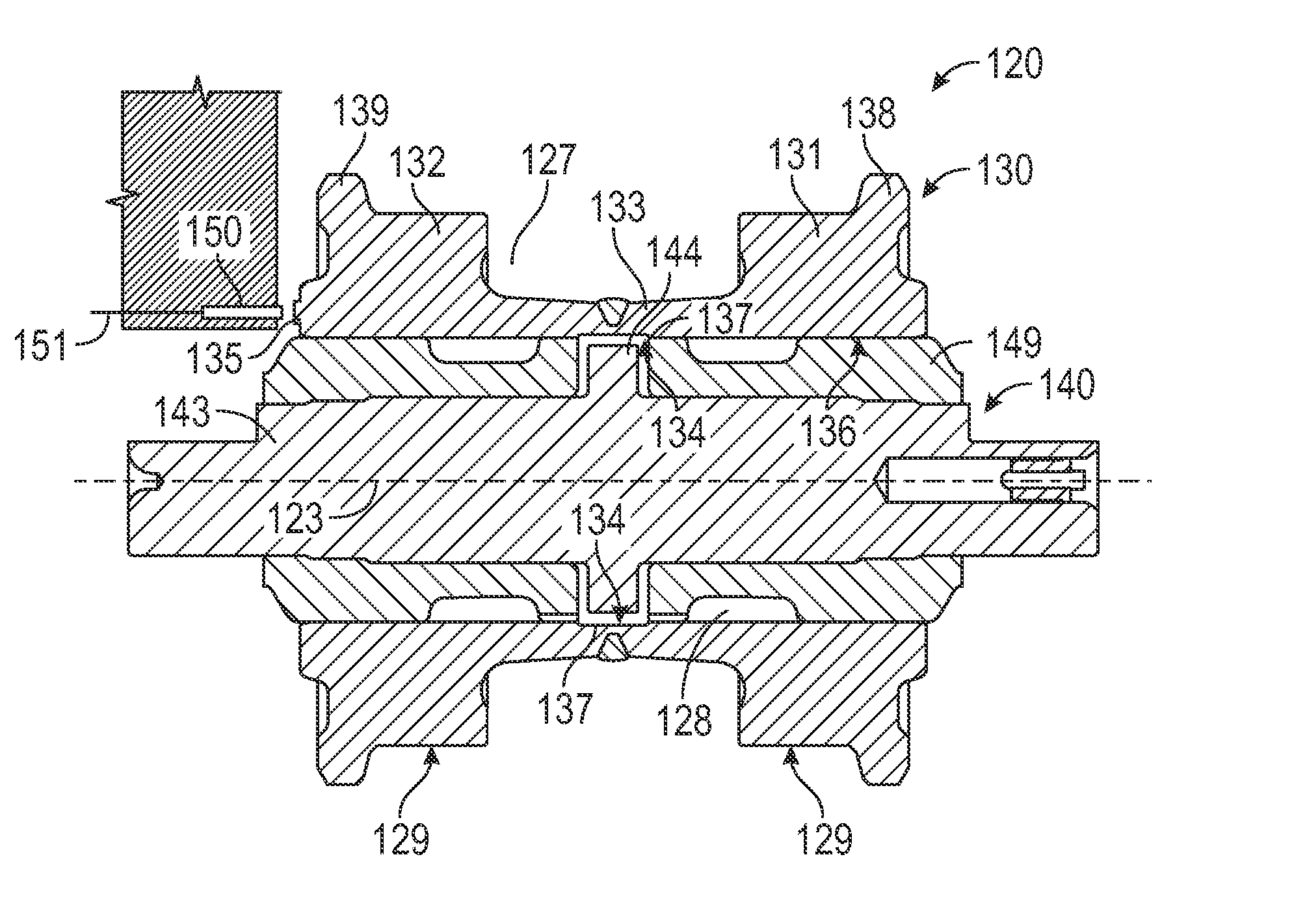
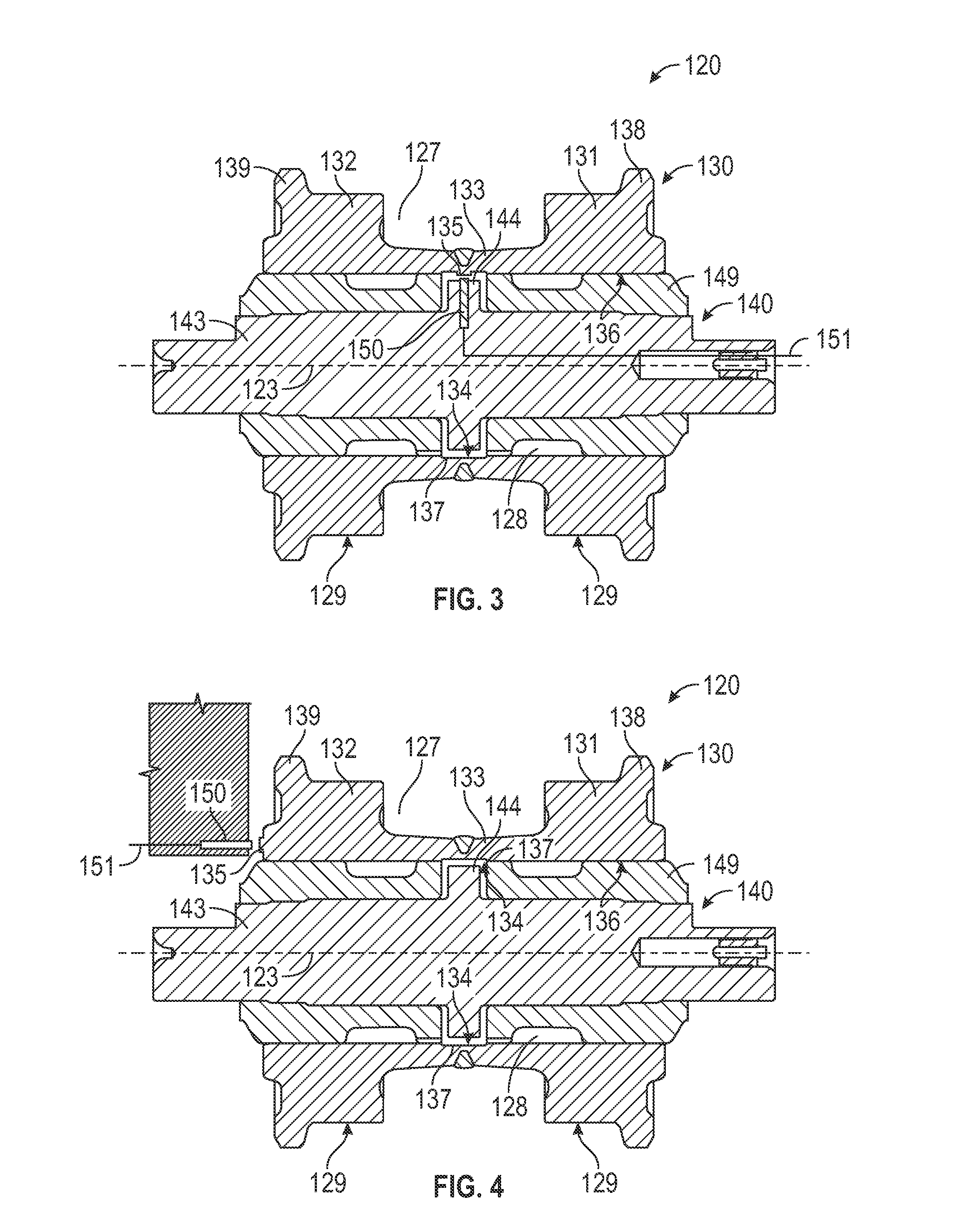
[0012]The systems and methods disclosed herein include a roller of an undercarriage track system for a machine. In embodiments, the roller includes a sensed feature that is detectable by a sensor. The sensor is configured to detect the sensed feature to track the revolutions of the roller. The revolutions tracked by the sensor may be used to determine a rotational speed of the roller, which can be compared to the translational speed of the machine to determine wear on the roller. Determining the wear on the roller may allow an operator or an original equipment manufacturer to predict further wear on the roller and to determine when to schedule maintenance on the machine.

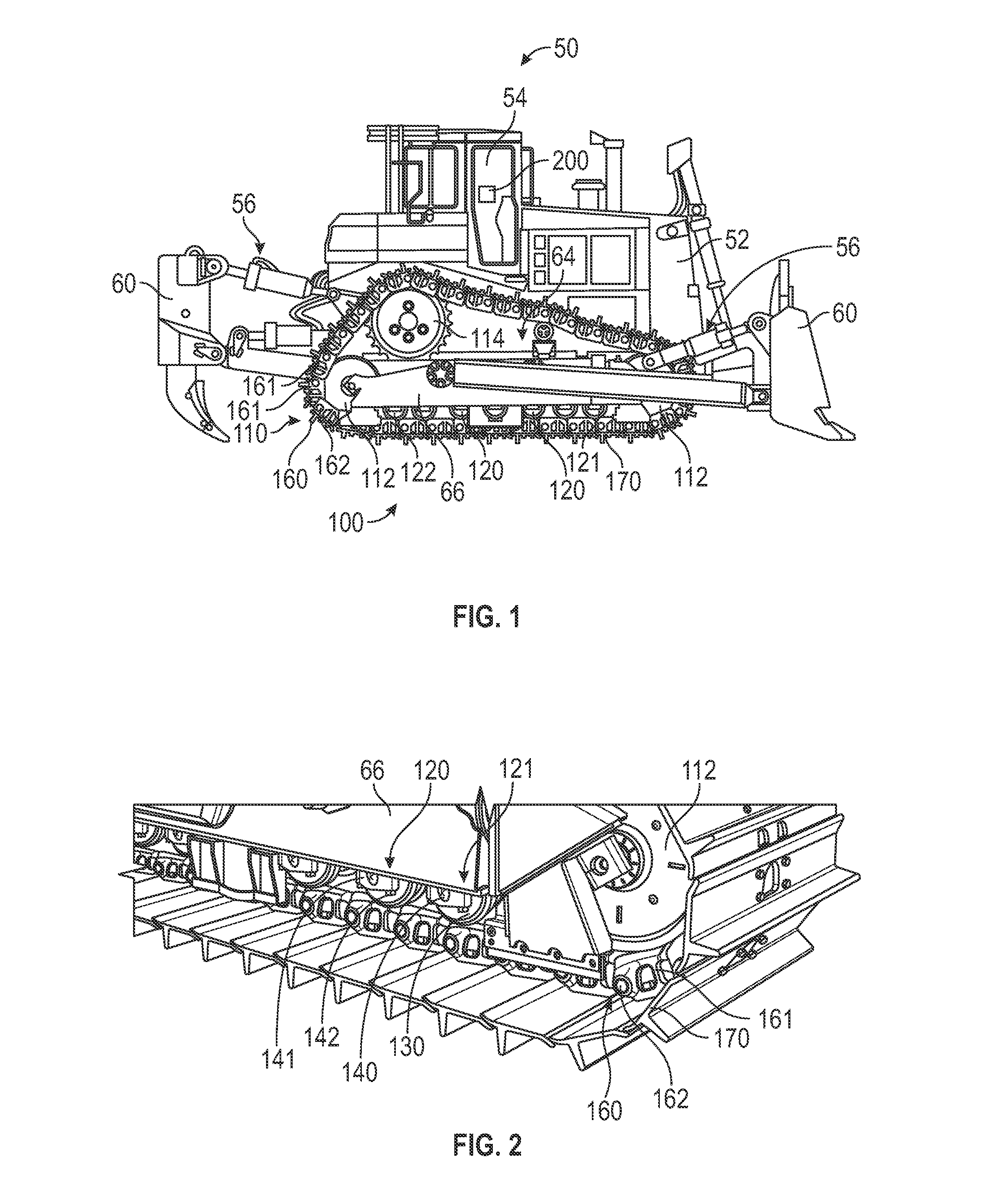
[0013]FIG. 1 is a diagrammatic side elevational view of an embodiment of a machine 50 including an undercarriage track system 100. The term “machine” may refer to any machine that that performs some type of operation associated with an industry such as mining or construction, or any other industry known in the art, ...


PUM


Abstract

A roller of an undercarriage track system for a machine is disclosed. The roller includes a body and a sensed feature. The body is a solid of revolution formed about a roller axis. The body includes a bore surface and a roller contact surface. The bore surface defines a bore extending through the body. The bore surface is a radially inner surface of the body. The roller contact surface is located outward from the bore surface. The sensed feature is located at the body. The sensed feature is configured to rotate with the body and to be detectable by a sensor.

Description

TECHNICAL FIELD[0001]The present disclosure generally pertains to undercarriage track systems, and is directed toward a track roller assembly with a wear measurement system for mining and construction machinery.BACKGROUND[0002]Mining and construction machines, such as hydraulic mining shovels, excavators, wheel loaders, cable shovels, bucket wheels, and draglines commonly employ undercarriage track systems. The undercarriage track systems generally employ a track chain assembly formed by interconnected track links. The track chain assembly is generally guided and supported by rollers. The contact between the track links and the rollers may create high stresses, which can cause, inter alia, wear along contact surfaces of the rollers and track links.[0003]The undercarriage track system may be monitored to determine when to service the undercarriage track system. U.S. Patent application No. 2013 / 0255354 to Hawkins et al., for example, discloses an undercarriage monitoring device having...

Claims


Application Information

Patent Timeline
IPC IPC(8): B62D55/14G01N3/56B62D55/15B62D55/08
CPCB62D55/14B62D55/15G01N3/56B62D55/08
Inventor RUST, CRAIG RICHARDDIEKEVERS, MARK STEVEN
Owner CATERPILLAR INC
Why Eureka
Try Eureka