Pneumatically-operated fluid pump with amplified fluid pressure, and related methods

a fluid pump and pneumatic operation technology, applied in the direction of positive displacement liquid engines, pump control, piston pumps, etc., can solve the problem of fluid being expelled from the subject fluid chamber, and achieve the effect of increasing and decreasing the volume of the subject fluid chamber

Inactive Publication Date: 2016-05-05
WHITE KNIGHT FLUID HANDLING
View PDF10 Cites 38 Cited by
  • Summary
  • Abstract
  • Description
  • Claims
  • Application Information

AI Technical Summary

Benefits of technology

[0005]In some embodiments, the present disclosure includes a fluid pump for pumping a subject fluid. The fluid pump may include a pump body, a first cavity within the pump body, a second cavity within the pump body, a piston shaft hole extending from the first cavity to the second cavity, and a flexible member disposed within the second cavity. The flexible member may include a tubular body having a first closed end and a second open end opposite the first closed end, the second open end being proximate the piston shaft hole. The fluid pump may include an incompressible fluid chamber defined within the second cavity on a first side of the flexible member. The incompressible fluid chamber may include an incompressible fluid disposed therein. The fluid pump may further include a subject fluid chamber between a second cavity interior surface of the second cavity and an exterior surface of the flexible member. The flexible member may be configured to increase and decrease a volume of the subject fluid chamber. The fluid pump may further include a piston. The piston may include a piston head having a first side and an opposite second side. The first side of the piston head may have a first surface area. The piston head may be movable within the first cavity. The piston may further include an elongated piston shaft extending from the second side of the piston head and at least partially into the piston shaft hole. The elongated piston shaft may have an end surface opposite the piston head. The end surface may have a second surface area smaller than the first surface area of the first side of the piston head.
[0006]In additional embodiments, the present disclosure includes a pump body for pumping a subject fluid. The pump body may include a flexible member disposed within the pump body. The flexible member may include a tubular body having a first closed end and a second open end opposite the first closed end. The flexible membe

Problems solved by technology

As the reciprocating piston moves in the opposite direction, the movement of the

Method used


Image

  • Pneumatically-operated fluid pump with amplified fluid pressure, and related methods
  • Pneumatically-operated fluid pump with amplified fluid pressure, and related methods
  • Pneumatically-operated fluid pump with amplified fluid pressure, and related methods

Examples


Embodiment Construction

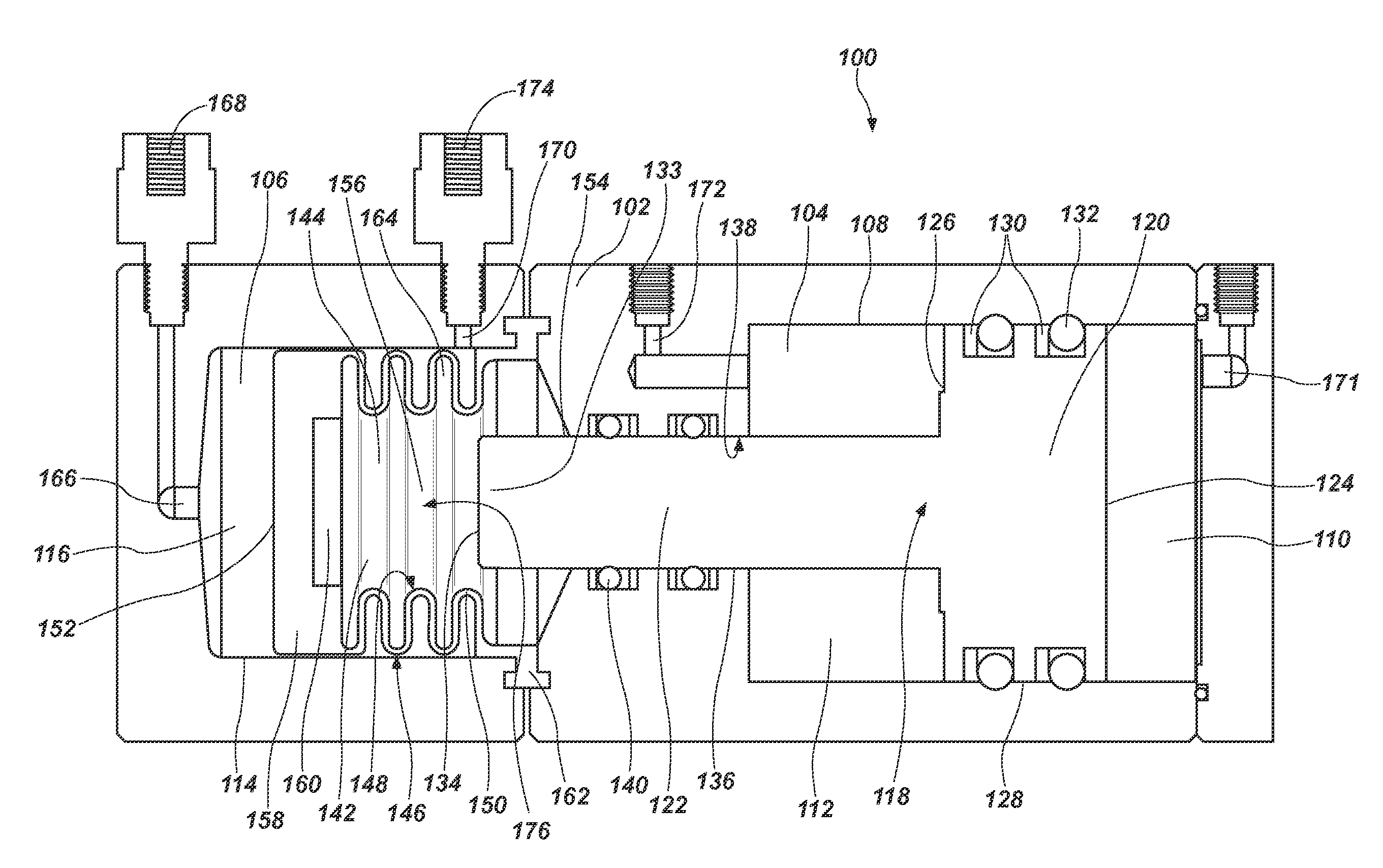
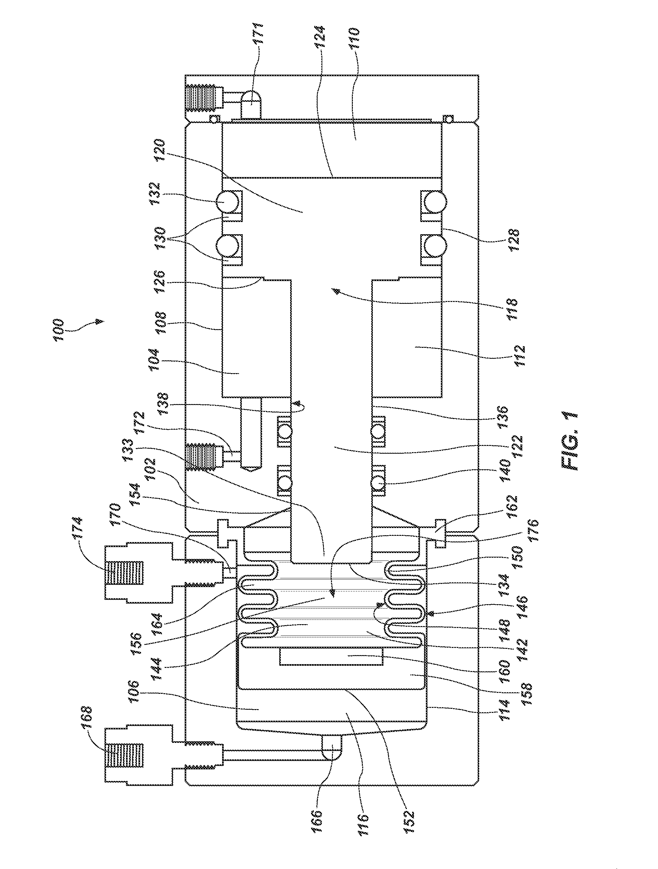
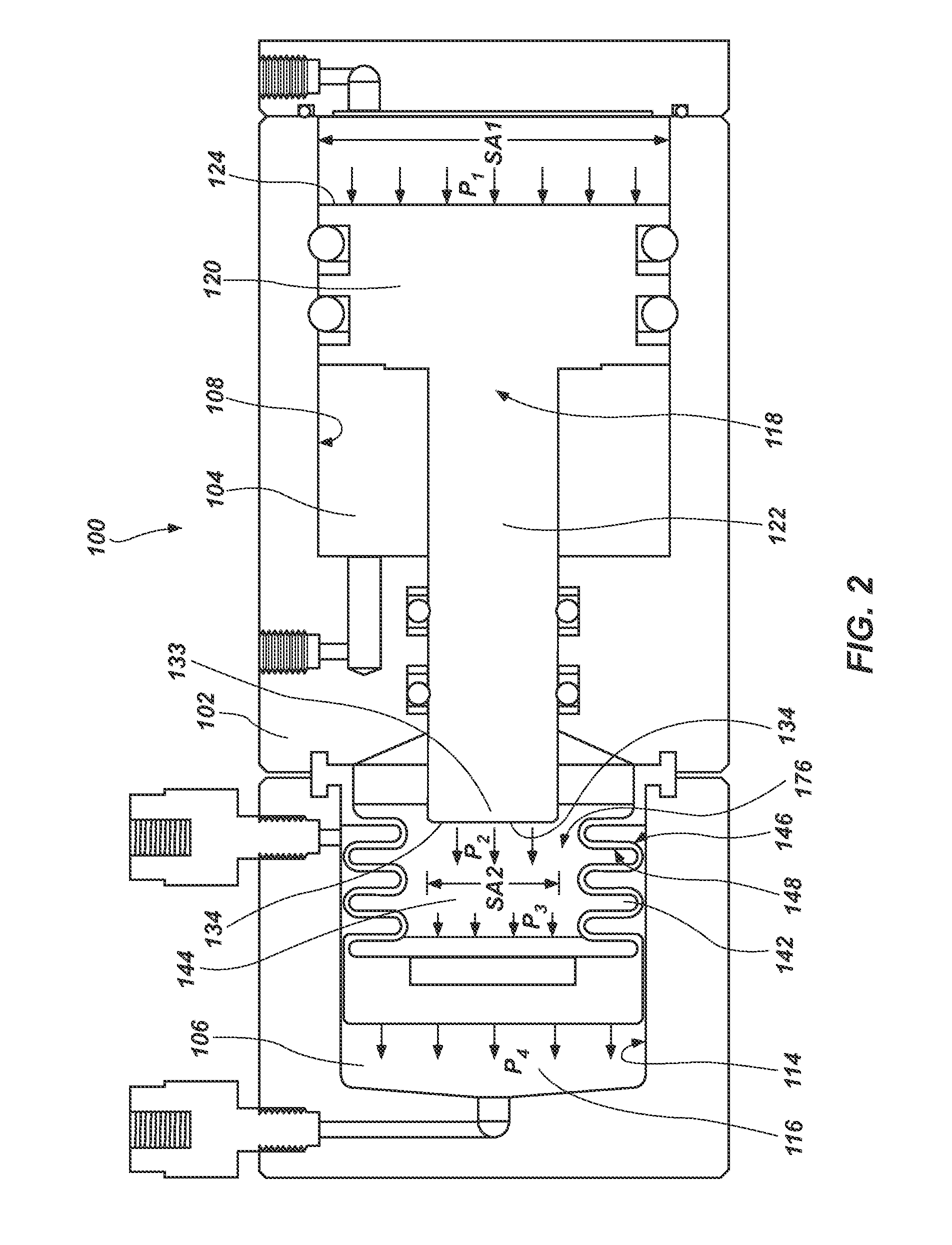
[0012]The illustrations presented herein are not meant to be actual views of any particular fluid pump 100 or component thereof, but are merely idealized representations that are used to describe embodiments of the disclosure.

[0013]As used herein, the term “substantially” in reference to a given parameter, property, or condition means and includes to a degree that one skilled in the art would understand that the given parameter, property, or condition is met with a small degree of variance, such as within acceptable manufacturing tolerances. For example, a parameter that is substantially met may be at least about 90% met, at least about 95% met, or even at least about 99% met.

[0014]Embodiments of the present disclosure include fluid pumps that include at least one drive fluid chamber, at least one subject fluid chamber, an incompressible fluid, a piston, and a flexible member for pressurizing a subject fluid to a pressure higher than a pressure to which a pressurized drive fluid is ...


PUM


Abstract

A fluid pump for pumping a subject fluid. The fluid pump including, a pump body, a first cavity within the pump body, a second cavity within the pump body, a flexible member, an incompressible fluid, a subject fluid chamber, and a piston. Piston may include a piston head and an elongated piston shaft. The piston may be configured to amplify a first pressure experienced on a first side of the piston head and exerted by a pressurized drive fluid to a second pressure experienced on an end surface of the elongated piston shaft and exerted on the incompressible fluid within the flexible member. The subject fluid may in turn be pressurized to a third pressure substantially equal to the second pressure.

Description

TECHNICAL FIELD[0001]Embodiments of the present disclosure relate generally to positive displacement devices. More particularly, embodiments of the present disclosure relate to pneumatically-operated fluid pumps and related methods.BACKGROUND[0002]Reciprocating fluid pumps are used in many industries. Reciprocating fluid pumps generally include two at least one fluid chamber in a pump body. A reciprocating piston or shaft is driven back and forth within the pump body. One or more flexible members may be connected to the reciprocating piston or shaft. As the reciprocating piston moves in one direction, the movement of the flexible members results in subject fluid being drawn into a subject fluid chamber. As the reciprocating piston moves in the opposite direction, the movement of the flexible members results in fluid being expelled from the subject fluid chamber. A subject fluid inlet and a subject fluid outlet may be provided in fluid communication with the subject fluid chamber. Ch...

Claims


Application Information

Patent Timeline
IPC IPC(8): F04B9/135
CPCF04B9/135F04B9/133F04B43/0054F04B43/067F04B45/02
Inventor SIMMONS, TOM M.
Owner WHITE KNIGHT FLUID HANDLING
Why Eureka
Try Eureka