
Liquid supply device and liquid ejecting apparatus

a liquid supply device and liquid ejector technology, which is applied in printing and other directions, can solve the problems of large absorbing member, ink contamination inside the printer, and ink leakage from the ink supply device,

Active Publication Date: 2012-05-29
SEIKO EPSON CORP
View PDF7 Cites 0 Cited by
  • Summary
  • Abstract
  • Description
  • Claims
  • Application Information

AI Technical Summary

Benefits of technology

[0010]An advantage of some aspects of the invention is that it provides a liquid supply device capable of suppressing an influence caused due to liquid leakage and a liquid ejecting apparatus including the liquid supply device.
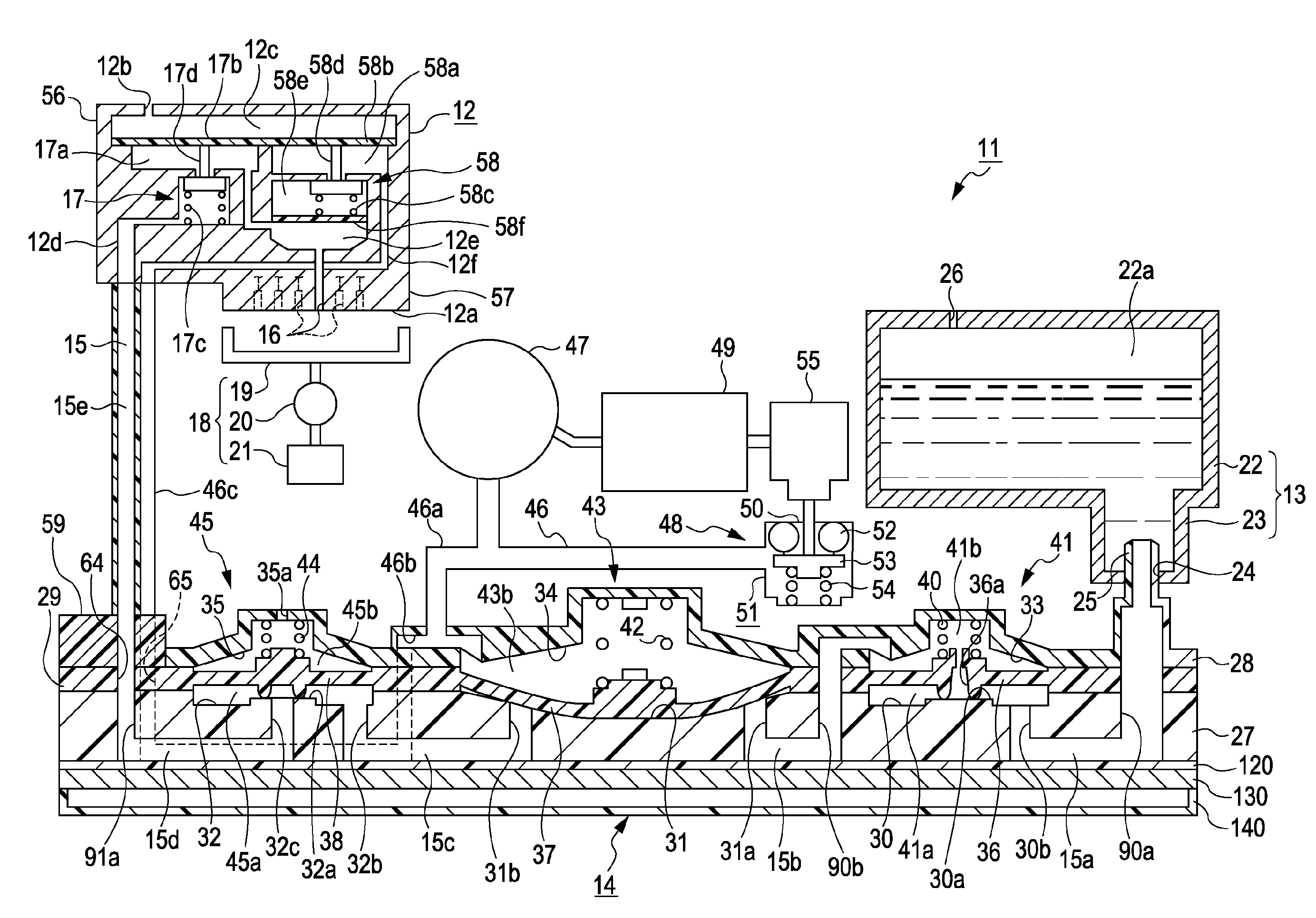
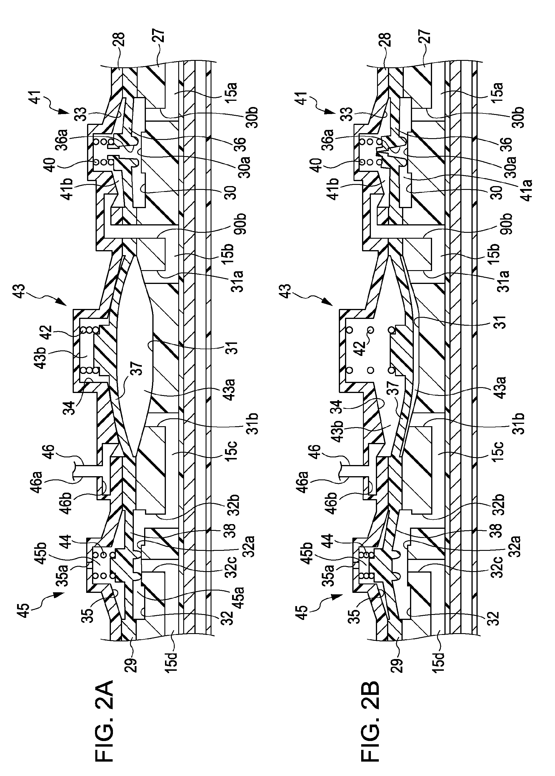
[0011]According to an aspect of the invention, there is provided a liquid supply device including: a liquid supply passage which supplies a liquid from an upstream side on which the liquid is supplied from a liquid supply source to a downstream side on which the liquid is consumed; a pump which is provided with a pump chamber in the liquid supply passage; a passage forming member which has a certain shape in which the liquid supply passage is formed; and a flexible diaphragm forming member which is provided with a diaphragm which forms a part of a wall surface of the pump chamber and is displaceable to increase or decrease the volume of the pump chamber. A lamination structure is formed by laminating the diaphragm forming member and the passage forming member so as to form the pump chamber between the facing surfaces thereof. A portion corresponding to the outer circumference of the diaphragm forming member in the lamination structure is provided with an outer circumference sealing portion which prevents the liquid, which has leaked from the liquid supply passage to a space between the facing surfaces of the diaphragm forming member and the passage forming member, from flowing outside the lamination structure.
[0012]With such a configuration, since the outer circumference sealing portion is provided in the portion corresponding to the outer circumference of the diaphragm forming member in the lamination structure, the liquid leaking from the liquid supply passage to a space between the diaphragm forming member and the passage forming member can be prevented from leaking to the outside of the lamination structure. Accordingly, even when plural liquid supply passages or plural pump chambers are formed in one lamination structure, the outer circumference sealing portion can collectively prevent the liquid from leaking. As a consequence, it is possible to suppress an influence caused due to the liquid leakage.

Problems solved by technology

Moreover, the ink which has leaked to the outside of the pump chamber from the gap may leak from the ink supply device formed in the lamination structure.
When the ink leaks from the ink supply device, a problem occurs in that the inside of the printer is contaminated by the ink.
This problem occurs not only in the above-described ink jet printer, but also in the liquid supply device, which supplies a liquid by use of the pump provided between the facing surfaces of the constituent members fixed in the laminated state so as to form a part of the liquid supply passage, and a liquid ejecting apparatus including the liquid supply device.
Moreover, a large absorbing member is required to absorb a large amount of ink.

Method used


Image

  • Liquid supply device and liquid ejecting apparatus
  • Liquid supply device and liquid ejecting apparatus
  • Liquid supply device and liquid ejecting apparatus

Examples


Embodiment Construction

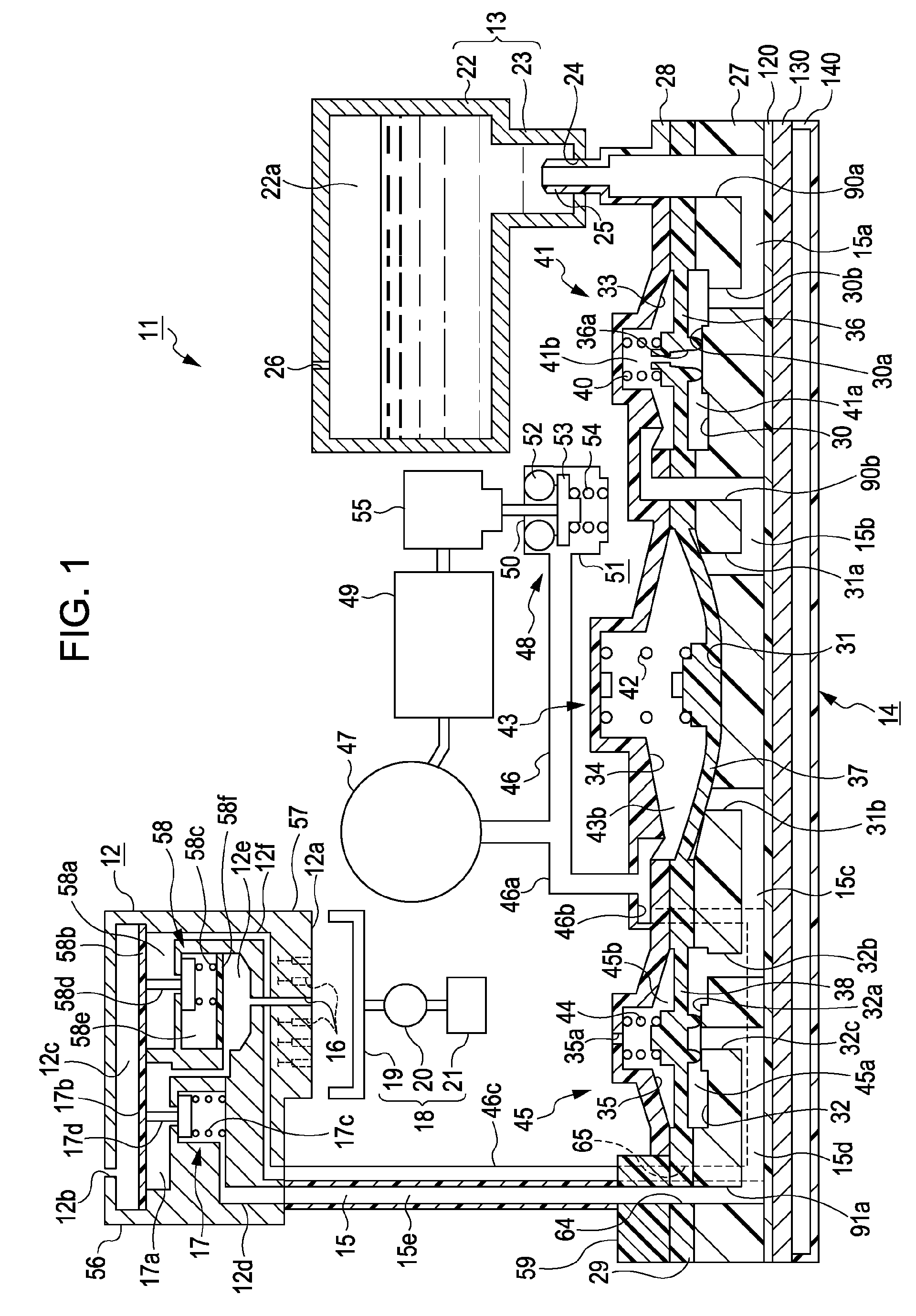
[0050]Hereinafter, an ink jet printer (hereinafter, referred to as “a printer”) which is an example of a liquid ejecting apparatus according to an embodiment of the invention will be described with reference to FIGS. 1 to 20.

[0051]As shown in FIG. 1, a printer 11 according to this embodiment includes a printing head unit 12 as a liquid ejecting unit which ejects ink (liquid) onto a target (for example, a print medium such as a sheet) (not shown) and an ink supply device 14 which supplies the ink stored in an ink cartridge 13 as a liquid supply source to the printing head unit 12. When the upstream end of the ink supply device is connected to the ink cartridge 13 and the downstream end of the ink supply device is connected to the printing head unit 12, a part of an ink passage 15 supplying the ink from an upstream side, which is the ink cartridge 13, to a downstream side, which is the printing head unit 12, is formed in the ink supply device 14.

[0052]The printer 11 according to this ...


PUM


Abstract

A liquid supply device includes a liquid supply passage which supplies a liquid from an upstream side where it is supplied from a liquid supply source to a downstream side where it is consumed. A passage forming member has a shape in which the liquid supply passage is formed. A flexible diaphragm forming member has a diaphragm forming part of a wall surface of a pump chamber in the liquid supply passage and is displaceable to change the volume of the pump chamber. A lamination structure is formed by laminating the diaphragm forming member and the passage forming member to form the pump chamber between facing surfaces thereof. A portion corresponding to the outer circumference of the diaphragm forming member has an outer circumference sealing portion preventing liquid, which has leaked from the liquid supply passage to a space between the facing surfaces, from flowing outside the lamination structure.

Description

BACKGROUND[0001]The entire disclosure of Japanese Patent Application No. 2008-190200, filed Jul. 23, 2008, is expressly incorporated herein by reference.[0002]1. Technical Field[0003]The present invention relates to a liquid supply device and a liquid ejecting apparatus.[0004]2. Related Art[0005]In the past, there was known an ink jet printer (hereinafter, referred to as “a printer”) as a liquid ejecting apparatus for ejecting a liquid onto a target. The printer performs printing on a print medium as the target by ejecting ink (a liquid) supplied to a printing head (a liquid ejecting unit) through nozzles formed in the printing head. In recent years, as disclosed in JP-A-5-185603, for example, there has been suggested a printer in which a pump driven to pressurize and supply ink to a printing head from an ink cartridge is formed in an ink passage (a liquid supply passage) connecting an ink tank (a liquid supply source) to the printing head.[0006]In the printer disclosed in JP-A-5-18...

Claims


Application Information

Patent Timeline
Patent Type & Authority Patents(United States)
IPC IPC(8): B41J2/175
CPCB41J2/175B41J2/1752B41J2/17553B41J2/17596
Inventor YOKOUCHI, HIDEYA
Owner SEIKO EPSON CORP
Learn More