Vehicle

a technology of vehicle and braking torque, which is applied in the field of vehicles, can solve the problems of deteriorating riding comfort of the driver, large regenerative origin noise, and relatively large regenerative noise, so as to reduce the braking torque of the resonance-side motor and prevent deterioration of the ride comfort of the driver

Active Publication Date: 2016-05-12
TOYOTA JIDOSHA KK
View PDF0 Cites 12 Cited by
  • Summary
  • Abstract
  • Description
  • Claims
  • Application Information

AI Technical Summary

Benefits of technology

[0007]The invention provides a vehicle that restrains the riding comfort of a driver from deteriorating during deceleration.
[0009]According to the aforementioned configuration, the front-wheel motor and the rear-wheel motor are controlled such that the vehicle runs with the required torque corresponding to accelerator operation and brake operation. Then, the front-wheel motor and the rear-wheel motor are controlled during deceleration caused by the braking torque (a regenerative torque) from the front-wheel motor and the braking torque (a regenerative torque) from the rear-wheel motor, in such a manner as to make the braking torque of the resonance-side motor, namely, that one of the front-wheel motor and the rear-wheel motor whose rotational speed is within the resonance range smaller at the time of predetermined resonance than at the time of predetermined non-resonance, and to make the braking torque of the non-resonance-side motor, namely, that one of the front-wheel motor and the rear-wheel motor whose rotational speed is outside the resonance range larger at the time of predetermined resonance than at the time of predetermined non-resonance. The rotational speed of the front-wheel motor or the rear-wheel motor is within the resonance range at the time of predetermined resonance, and the rotational speeds of the front-wheel motor and the rear-wheel motor are outside the resonance range at the time of predetermined non-resonance. Accordingly, the braking torque of the resonance-side motor is made smaller, so a noise resulting from regenerative driving of the front-wheel motor or the rear-wheel motor can be restrained from being perceived by the driver. As a result, the riding comfort of the driver can be restrained from deteriorating.
[0010]In the vehicle, the electronic control unit may be configured to control the front-wheel motor and the rear-wheel motor during the deceleration, such that an amount of reduction in the braking torque of the resonance-side motor and an amount of increase in the braking torque of the non-resonance-side motor, when at least one of the rotation speed of the front-wheel motor and the rotation speed of the rear-wheel motor is within a resonance range at which at least one of the front-wheel motor and the rear-wheel motor resonates, increase more as a vehicle speed decreases, than the amount of reduction in the braking torque of the resonance-side motor and the amount of increase in the braking torque of the non-resonance-side motor when the rotation speed of the front-wheel motor and the rotation speed of the rear-wheel motor are outside the resonance range at which the front-wheel motor and the rear-wheel motor does not resonates. According to the aforementioned configuration, a noise resulting from regenerative driving of the front-wheel motor or the rear-wheel motor can be more reliably restrained from being perceived by the driver.
[0013]In the vehicle, the electronic control unit may be configured to increase a ratio of a torque of the rear wheel to a sum of a torque of the front wheel and the torque of the rear wheel as a brake operation amount increases, during the deceleration. As the brake operation amount increases, the deceleration increases, and the likelihood of the vehicle assuming a forward-bent posture increases. According to the aforementioned configuration, the vehicle can be restrained from assuming a forward-bent posture. As a result, the stability of the running posture of the vehicle can be restrained from decreasing.

Problems solved by technology

Therefore, when the rotational speed of the second generator-motor is within the resonance range, the regeneration-originated noise may become relatively large and perceptible to a driver.
Thus, the riding comfort of the driver may be deteriorated.

Method used


Image

  • Vehicle
  • Vehicle
  • Vehicle

Examples


Embodiment Construction

[0025]Next, the embodiment of the invention will be described using the drawings.

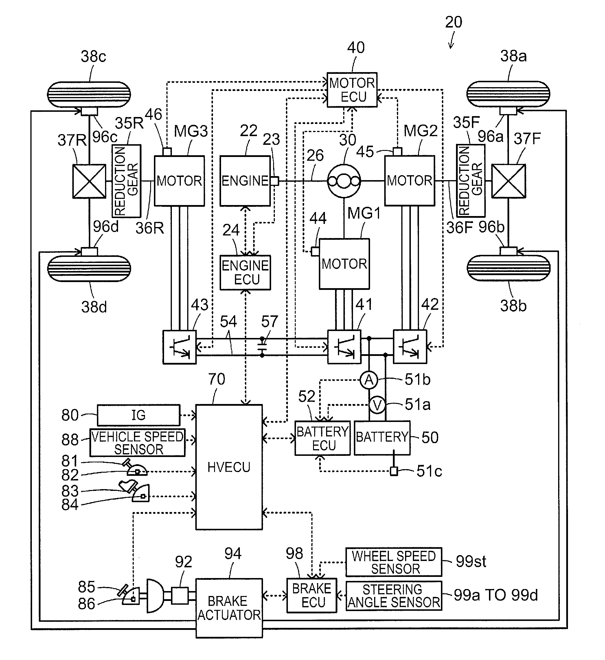
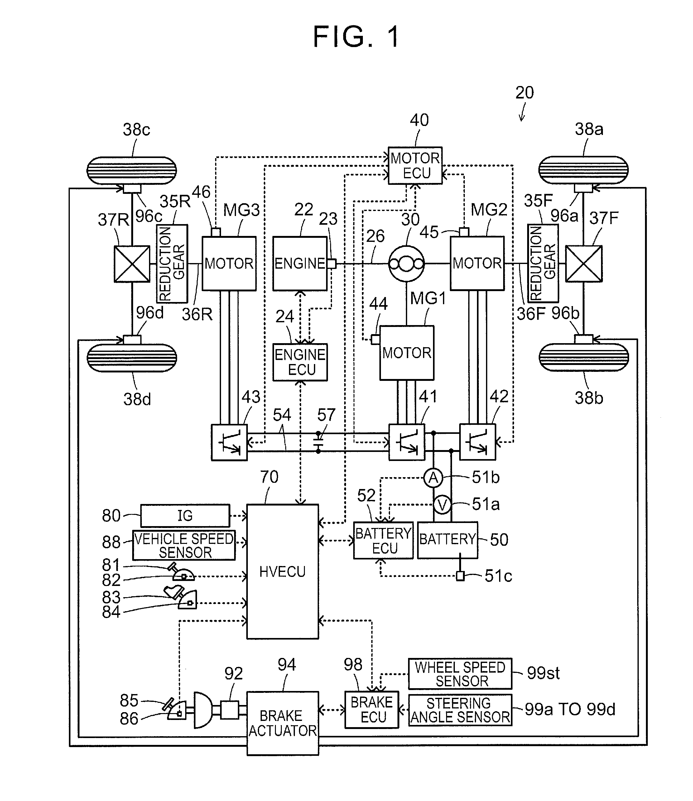
[0026]FIG. 1 is a block diagram showing the schematic configuration of a hybrid vehicle 20 in the embodiment of the invention. As shown in the drawing, the hybrid vehicle 20 is equipped with an engine 22, a planetary gear 30, motors MG1, MG2, MG3, inverters 41, 42, 43, a battery 50, a brake actuator 94, and a hybrid electronic control unit (hereinafter referred to as an HVECU) 70.

[0027]The engine 22 is an internal combustion engine that outputs motive power using gasoline, light oil or the like as fuel. The operation of this engine 22 is controlled by an engine electronic control unit (hereinafter referred to as an engine ECU) 24.

[0028]Although not shown in the drawing, the engine ECU 24 is configured as a microprocessor that is mainly constituted of a CPU. In addition to the CPU, the engine ECU 24 is equipped with a ROM that stores processing programs, a RAM that temporarily stores data, receive / output...


PUM


Abstract

A vehicle includes a front-wheel / rear-wheel motor, a battery and an ECU. The ECU is configured to (i) control the front-wheel / rear-wheel motors, and (ii) control the front-wheel / rear-wheel motors such that a braking torque of a resonance-side motor, when at least one of the rotation speed of the front-wheel / rear-wheel motors is within a resonance range, is smaller than the braking torque of the resonance-side motor, when the rotation speed of the front-wheel / rear-wheel motors are outside the resonance range, and such that the braking torque of a non-resonance-side motor, when at least one of the rotation speed of the front-wheel / rear-wheel motors is within a resonance range, is larger than the braking torque of the non-resonance-side motor, when the rotation speed of the front-wheel / rear-wheel motors are outside the resonance range, during deceleration caused by a braking torque from the front-wheel / rear-wheel motors.

Description

INCORPORATION BY REFERENCE[0001]The disclosure of Japanese Patent Application No. 2014-227130 filed on Nov. 7, 2014 including the specification, drawings and abstract is incorporated hereinby reference in its entirety.BACKGROUND OF THE INVENTION[0002]1. Field of the Invention[0003]The invention relates to a vehicle that is equipped with a first-wheel motor that can receive / output motive power to / from front wheels, a rear-wheel motor that can receive / output motive power to / from rear wheels, and a battery that can exchange electric power with the front-wheel motor and the rear-wheel motor.[0004]2. Description of Related Art[0005]In Japanese Patent Application Publication No. 2005-151633 (JP 2005-151633 A), there is disclosed a vehicle that is equipped with an engine, a first generator-motor, a second generator-motor and a brake mechanism. The first generator-motor is connected to the engine and is connected to front wheels via a transmission. The second generator-motor is connected to...

Claims


Application Information

Patent Timeline
Patent Type & Authority Applications(United States)
IPC IPC(8): B60L15/20B60W20/00
CPCB60L15/2036B60W20/00B60W2710/083Y10S903/903B60W2720/30B60W2540/10B60W2540/12B60W2720/403B60K6/445B60K6/52B60W30/18109B60W30/18127B60W30/20B60W20/14B60W20/17B60L7/18B60L15/2009B60L2220/42Y02T10/62Y02T10/64Y02T10/72
Inventor TAKAHASHI, YOSHIMITSU
Owner TOYOTA JIDOSHA KK
Why Eureka
Try Eureka