Group dynamic environment control

a dynamic environment and control system technology, applied in the field of environmental control, can solve the problems of high user discomfort in the hvac system utilizing average thermal comfort levels

Active Publication Date: 2016-05-12
CARRIER CORP
View PDF9 Cites 31 Cited by
  • Summary
  • Abstract
  • Description
  • Claims
  • Application Information

AI Technical Summary

Benefits of technology

[0009]FIG. 1 is a diagram of an environmenta

Problems solved by technology

However, HVAC systems utilizing average thermal comf

Method used


Image

  • Group dynamic environment control
  • Group dynamic environment control
  • Group dynamic environment control

Examples


Embodiment Construction

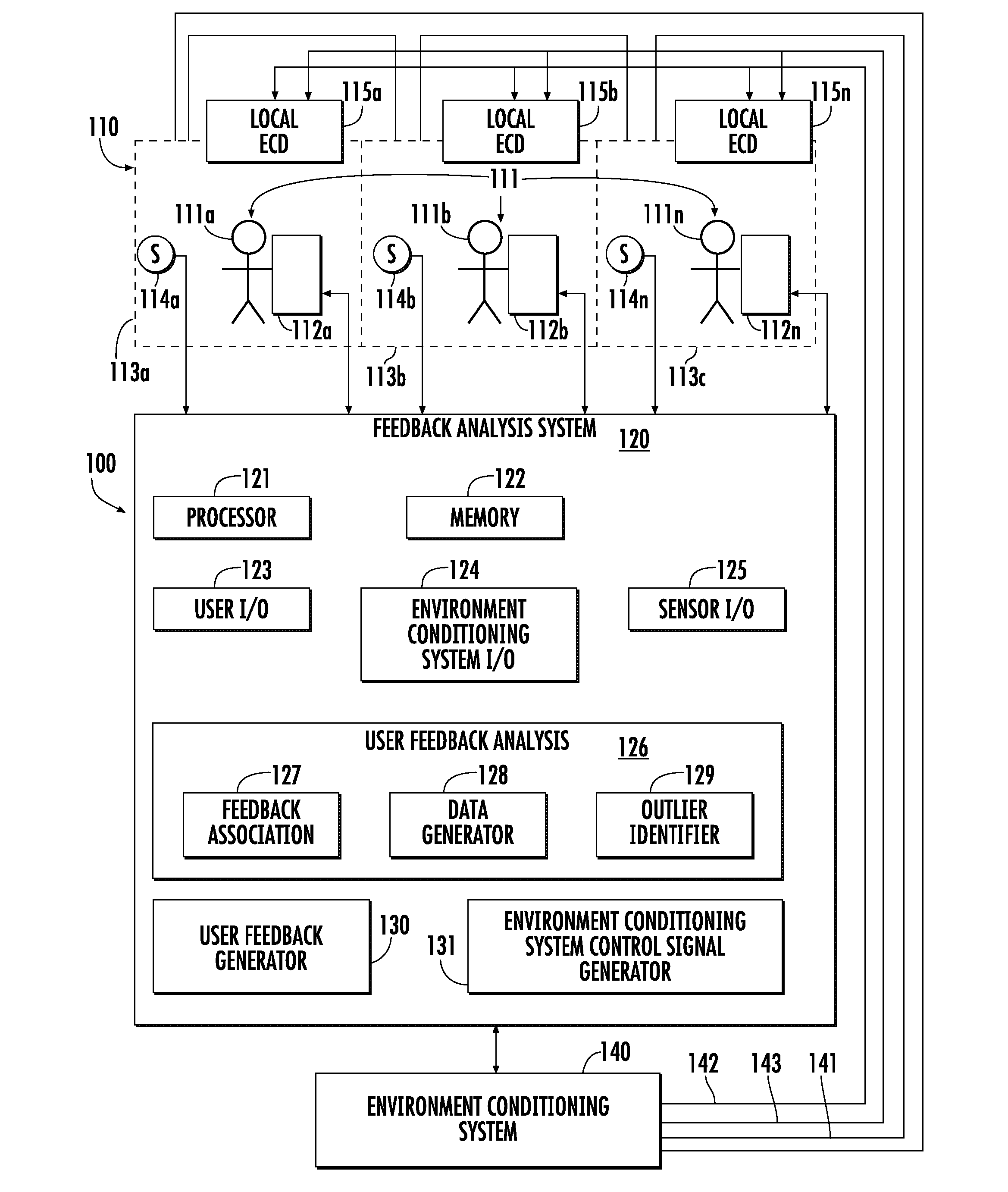
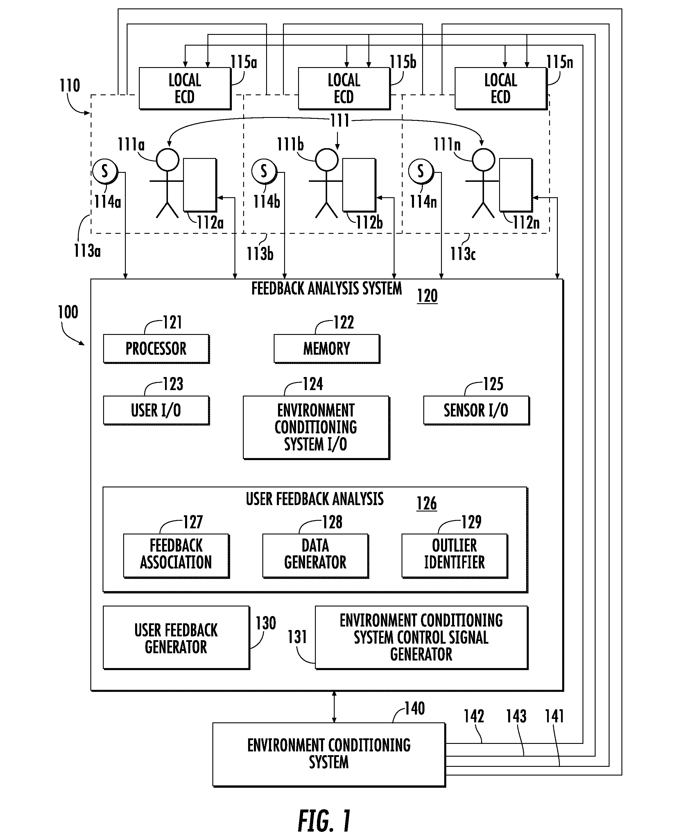
[0013]Conventional environmental control systems may not provide control to individual users when the system provides environmental conditioning for a group of users. Embodiments relate to an environmental conditioning system that conditions the environment in which a group of users is located based on analyzing feedback from multiple users in the environment.

[0014]FIG. 1 is a block diagram of an environmental control system 100 according to an embodiment of the invention. The environmental control system includes a group environment 110 or zone in which a plurality of users 111a, 111b . . . 111n, also referred to as a group 111 of users, is located. The group environment 110 may be made up of distinct regions, or individual environments 113a, 113b . . . 113n corresponding to the users 111a, 111b . . . 111n. The individual environments 113a to 113n are geographic regions associated with each user 111a to 111n. Examples of geographic regions include separate offices, separate cubicle...


PUM


Abstract

A method of conditioning an environment includes generating, by a group feedback analysis system, a first comfort limit based on a first plurality of data points corresponding to user feedback of a group of users in an environment conditioned by an environmental conditioning system to identify the first comfort limit at a first extreme; generating, by the group feedback analysis system, a second comfort limit based on a second plurality of data points corresponding to user feedback of the group of users in the environment conditioned by the environmental conditioning system to identify the second comfort limit at a second extreme, the second extreme being opposite the first extreme; identifying, by the group feedback analysis system, a comfort region defined by the first comfort limit and the second comfort limit; and controlling the environmental conditioning system to maintain at least one environmental criterion within the comfort region.

Description

CROSS-REFERENCE TO RELATED APPLICATIONS[0001]This application claims priority to Chinese Patent Application 201410643746.4, with Chinese filing date of Nov. 10, 2014, and all the benefits accruing therefrom under 35 U.S.C. §119, the contents of which in its entirety are herein incorporated by reference.BACKGROUND OF THE INVENTION[0002]Embodiments relate to environment control, and in particular to group dynamic environmental control systems, methods, and apparatuses.[0003]Environmental control systems, such as heating, ventilating, and air-conditioning (HVAC) systems maintain high standards of service by keeping the environment in a building within the comfort zone of occupants of the building. One method for quantifying the comfort level of occupants is the predicted mean vote-predicted percent dissatisfied (PMV-PPD) model. The PMV-PPD model quantifies the thermal comfort concept as a mapping from environmental factors, such as air temperature, radiant temperature, relative humidit...

Claims


Application Information

Patent Timeline
IPC IPC(8): F24F11/00G05B13/02F24F11/02
CPCF24F11/006F24F11/0034F24F11/0076F24F11/02F24F2011/0068F24F2011/0035F24F2011/0036F24F2011/0057F24F2011/0061G05B13/0205F24F2120/10F24F2120/12F24F2120/14F24F2120/20F24F11/62F24F11/63F24F11/30F24F11/52F24F11/64F24F11/58F24F2120/00F24F11/47
Inventor ZHAO, QIANCHUANCHENG, ZHIJINWANG, FULINJIANG, YIDING, JINLEIREEVE, HAYDENBERTUCCELLI, LUCA F.
Owner CARRIER CORP
Why Eureka
Try Eureka