
Techniques for high arrival angle resolution using multiple nano-radars

a nano-radar and angle resolution technology, applied in the field of radar systems, can solve the problems of unmodulated signal, inapplicability, loss, etc., and achieve the effects of eliminating the many disadvantages of conventional, costly external antenna arrangements, and avoiding the extensive radar chip customization

Active Publication Date: 2016-05-26
TEXAS INSTR INC
View PDF7 Cites 192 Cited by
  • Summary
  • Abstract
  • Description
  • Claims
  • Application Information

AI Technical Summary

Benefits of technology

The present invention solves the problem of having to customize every radar chip when using long receive antenna arrays. Instead, the invention uses a plurality of standard radar chips that are tiled together, which eliminates the need for costly external antenna arrangements and reduces the disadvantages of conventional systems. The technical effect is an improved and more efficient solution for long receive antenna arrays.

Problems solved by technology

A simple unmodulated signal can only detect the velocity and not range of a single object, and hence is not useful in applications where both range and relative velocity of multiple objects need to be simultaneously determined.
External lines and connectors design to support signals at such high frequencies are very specialized, very lossy and very costly, as is circuit board routing of such signals.
However, limitations on the number of channels on a single chip and the package size can limit the number of antennas that can be integrated in this way.
In addition, the limited number of antennas can in turn limit the angle resolution achievable with such a radar apparatus.
However, even though radar chip 402 and radar chip 404 are tiled together as closely as possible, the distance D as indicated by arrowed line 405 is much too large for the antennas to form a usable array across all four antennas, and this arrangement would not work.
It has already been explained that in attempting to employ multiple radar chips to form the long receive antenna arrays required for the high arrival angle resolutions needed by common applications, the use of external antennas is a difficult and very costly approach.
It has also been explained how solutions which use multiple radar chips with integrated antennas are severely limited by necessary restrictions on chip size, antenna spacing and chip spacing.

Method used


Image

  • Techniques for high arrival angle resolution using multiple nano-radars
  • Techniques for high arrival angle resolution using multiple nano-radars
  • Techniques for high arrival angle resolution using multiple nano-radars

Examples


Embodiment Construction

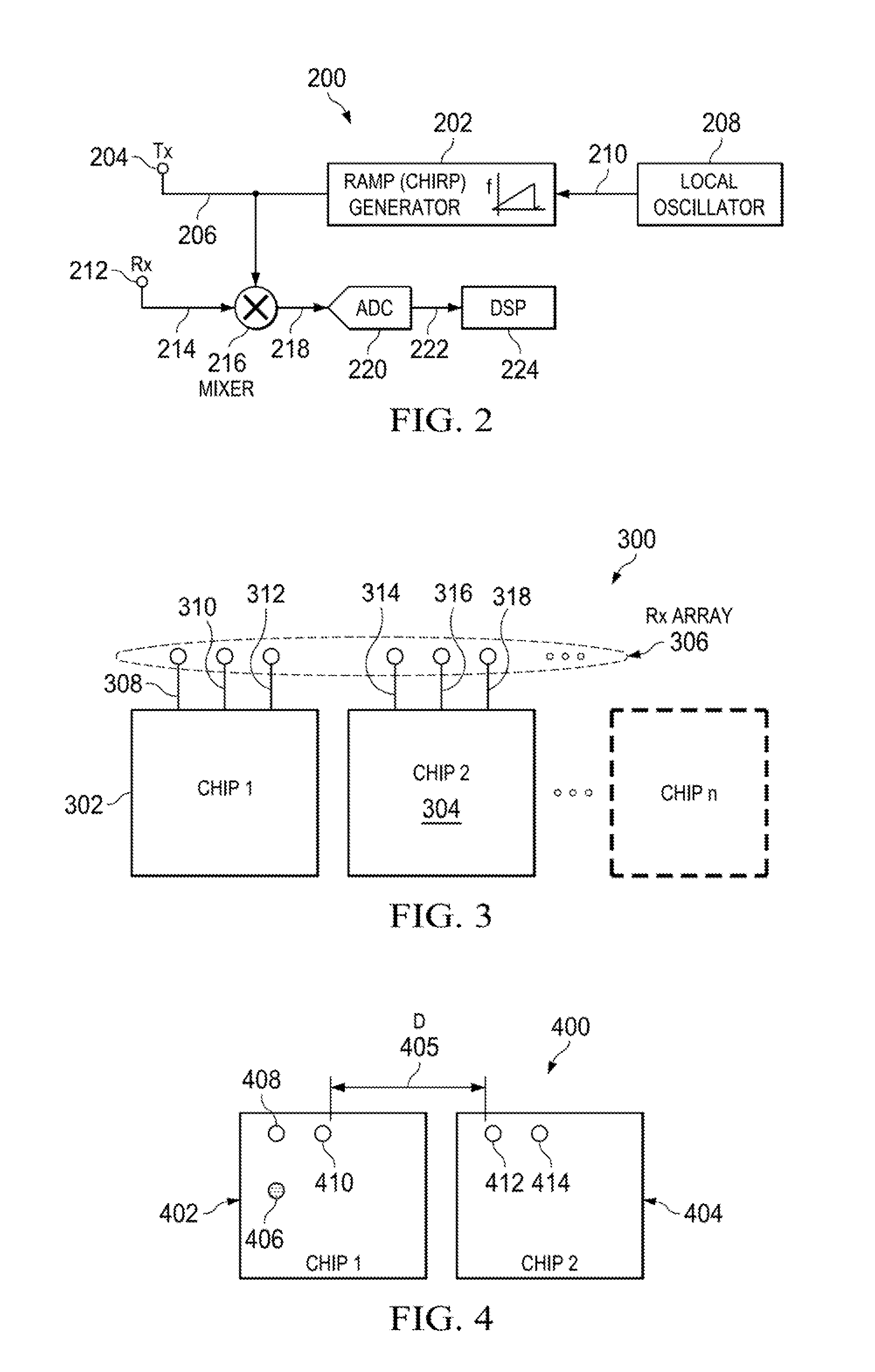
[0052]Aspects of the present invention are drawn to a technique known as “Sparse Antennas,” used in the context of tiling a plurality of standard radar chips to form long receive antenna arrays.

[0053]One aspect of the present invention is drawn to the use of one or more standard radar chips containing two or more embedded receive antennas together with one or more standard radar chips containing two or more embedded receive antennas as well as two or more embedded transmit antennas, all chips being arranged in a tiled configuration. The configuration operates together with an implementation of the sparse antenna technique to fill large gaps between “real” embedded receive antennas with “virtual” antennas. This produces a receive antenna array consisting of a number of both real and virtual antennas but which is mathematically equivalent to an array of the same number of real antennas.

[0054]Other aspects of the present invention are drawn to additional systems and methods designed to...


PUM


Abstract

A device includes a circuit board having thereon, a controlling component, a first radar chip and a second radar chip. The first radar chip includes a first radar transmission antenna, a second radar transmission antenna and a first radar receiver antenna array. The second radar chip includes a second radar receiver antenna array. The controlling component can control the first radar chip and the second radar chip. The first radar transmission antenna can transmit a first radar transmission signal. The second radar transmission antenna can transmit a second radar transmission signal. The second radar chip is spaced from the first radar chip so as to create a virtual receiver antenna array between the first radar receiver antenna array and the second radar receiver antenna array.

Description

BACKGROUND[0001]The present invention relates generally to radar systems intended for a variety of applications including automotive and industrial applications.[0002]A radar apparatus transmits a radar signal, which is reflected from multiple obstacles to create a received signal. The radar apparatus uses the received signal to estimate the distance, the velocity and the angle of arrival of these obstacles.[0003]Continuous-Wave (CW) radars transmit either an unmodulated or modulated frequency carrier as the radar signal. A simple unmodulated signal can only detect the velocity and not range of a single object, and hence is not useful in applications where both range and relative velocity of multiple objects need to be simultaneously determined. In order to measure range, modulation of the radar signal is essential.[0004]Frequency chirp architecture is the most popular of the automotive CW radars. In frequency-chirped radars, the frequency of the radar signal is varied according to ...

Claims


Application Information

Patent Timeline
IPC IPC(8): G01S13/02G01S7/02G01S13/931
CPCG01S7/02G01S13/02G01S13/343G01S13/931H01Q1/3233G01S7/032
Inventor RAO, SANDEEPRAMASUBRAMANIAN, KARTHIKGINSBURG, BRIANTANGUDU, JAWAHARLALSUBBARAJ, KARTHIK
Owner TEXAS INSTR INC
Features
  • Generate Ideas
  • Intellectual Property
  • Life Sciences
  • Materials
  • Tech Scout
  • Unparalleled Data Quality
  • Higher Quality Content
  • 60% Fewer Hallucinations
Learn More