Pneumatic tire

a pneumatic tire and groove technology, applied in the field of pneumatic tires, can solve the problems of affecting the stability of the steering wheel, the inability of the narrow groove to serve as drainage, and the occurrence of aquaplaning phenomena, so as to improve the steering stability, and maintain the width of the groove.

Active Publication Date: 2016-06-02
SUMITOMO RUBBER IND LTD
View PDF5 Cites 34 Cited by
  • Summary
  • Abstract
  • Description
  • Claims
  • Application Information

AI Technical Summary

Benefits of technology

[0077]The sipe-like narrow portion 12 in this example extends straight, and is inclined with respect to the tire axial direction. Such sipe-like narrow portion 12 exerts edge effect in the tire circumferential direction and tire axial direction. In order to effectively derive the above-mentioned advantageous effects, the angle θ1 of the sipe-like narrow portion 12 with respect to the tire axial direction is preferably set in a range of not less than 40 degrees, more preferably not less than 45 degrees, but, not more than 55 degrees, more preferably not more than 50 degrees.
[0078]As shown in FIG. 5(a), the sipe-like narrow portion 12 extends radially inwardly from the ground contacting surface 7s of the middle land zone 7 to its bottom which is rounded in this example, while keeping a constant groove width.
[0079]The groove width w3 of the sipe-like narrow portion 12 is preferably set in a range of not more than 1.8 mm, more preferably not more than 1.5 mm, but not less than 0.3 mm, more preferably not less than 0.5 mm in order to improve the steering stability on dry roads and the wet performance well balancedly.
[0080]The wide portion 14 has opposite groove-walls which are a first groove-wall 18 on one side in the tire circumferential direction, and a second groove-wall 19 on the other side in the tire circumferential direction, wherein, as shown in FIG. 5(b), in the cross section perpendicular to the longitudinal direction of the groove, the first groove-wall 18 partly extends substantially parallel with the tire radial direction, and partly inclines with respect to the tire radial direction to have a gentle slope part 20, whereas the second groove-wall 19 all extends substantially parallel with the tire radial direction. Thereby, the wide portion 14 comprises a radially outermost tapered part 21 in which the groove width gradually decreases toward the radially inside of the tire, and a radially inner part 22 extending from the tapered part 21 toward the radially inside of the tire while keeping a groove width equal to the groove width of the sipe-like narrow portion 12.
[0081]The angle θ2 of the gentle slope part 20 with respect to the tire radial direction is preferably set in a range of not less than 20 degrees, more preferably not less than 25 degrees, but, not more than 40 degrees, more preferably not more than 45 degrees. Such gentle slope part 20 exerts good drainage, while preventing uneven wear around the tapered part 21.
[0082]In this example, the gentle slope part 20 is continued to the groove-wall of the radially inner part 22 through a smoothly curved surface. However, the gentle slope part 20 is not limited to such configuration. It may be possible that the gentle slope part 20 is a flat surface extending from the ground contacting surface 7s of the middle land zone 7 to the radially inner part 22.

Problems solved by technology

Accordingly, the narrow grooves can not serve for drainage, and aquaplaning phenomenon is liable to occur when running on wet roads at high speed.

Method used


Image

  • Pneumatic tire
  • Pneumatic tire
  • Pneumatic tire

Examples


working examples

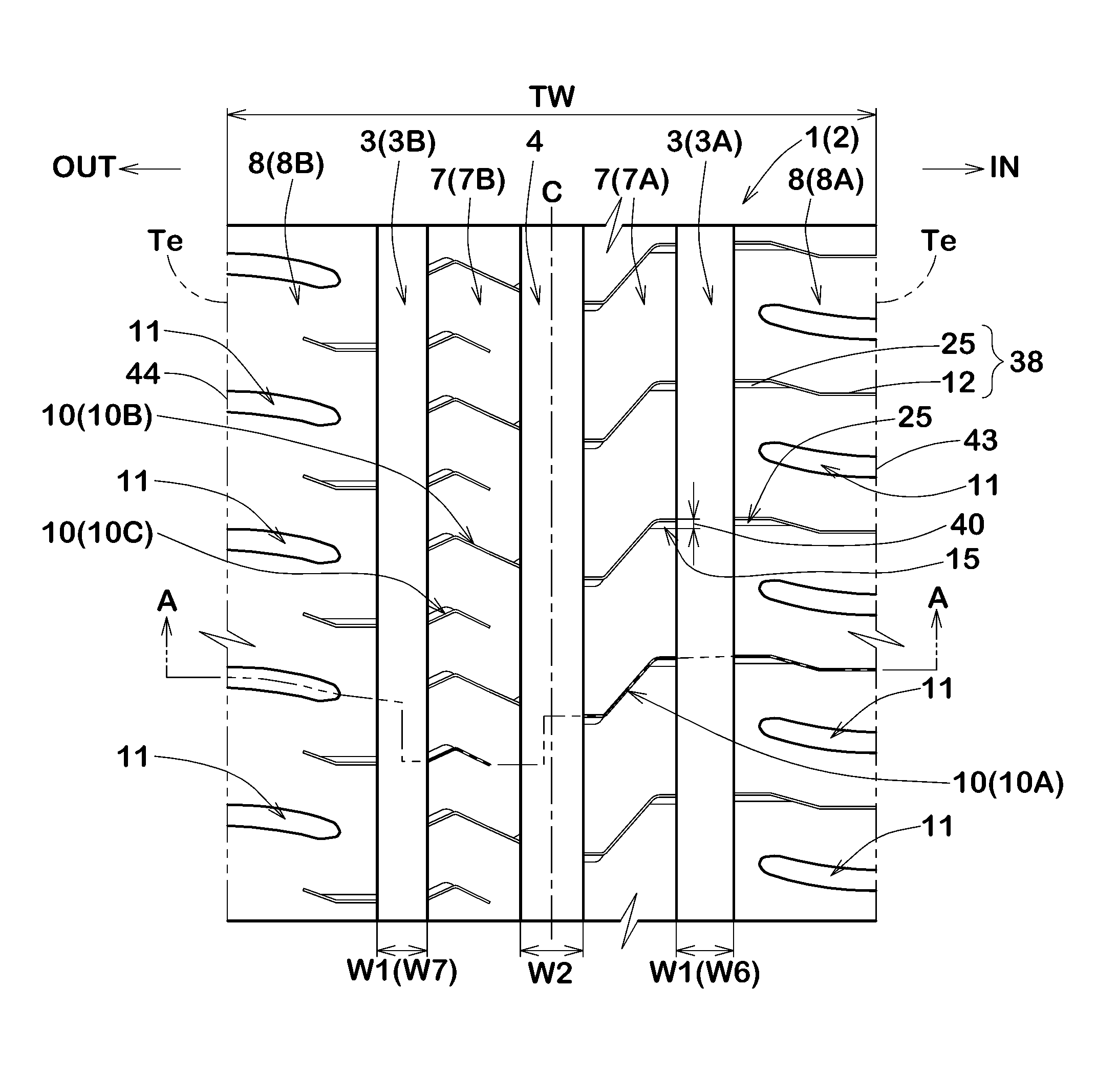
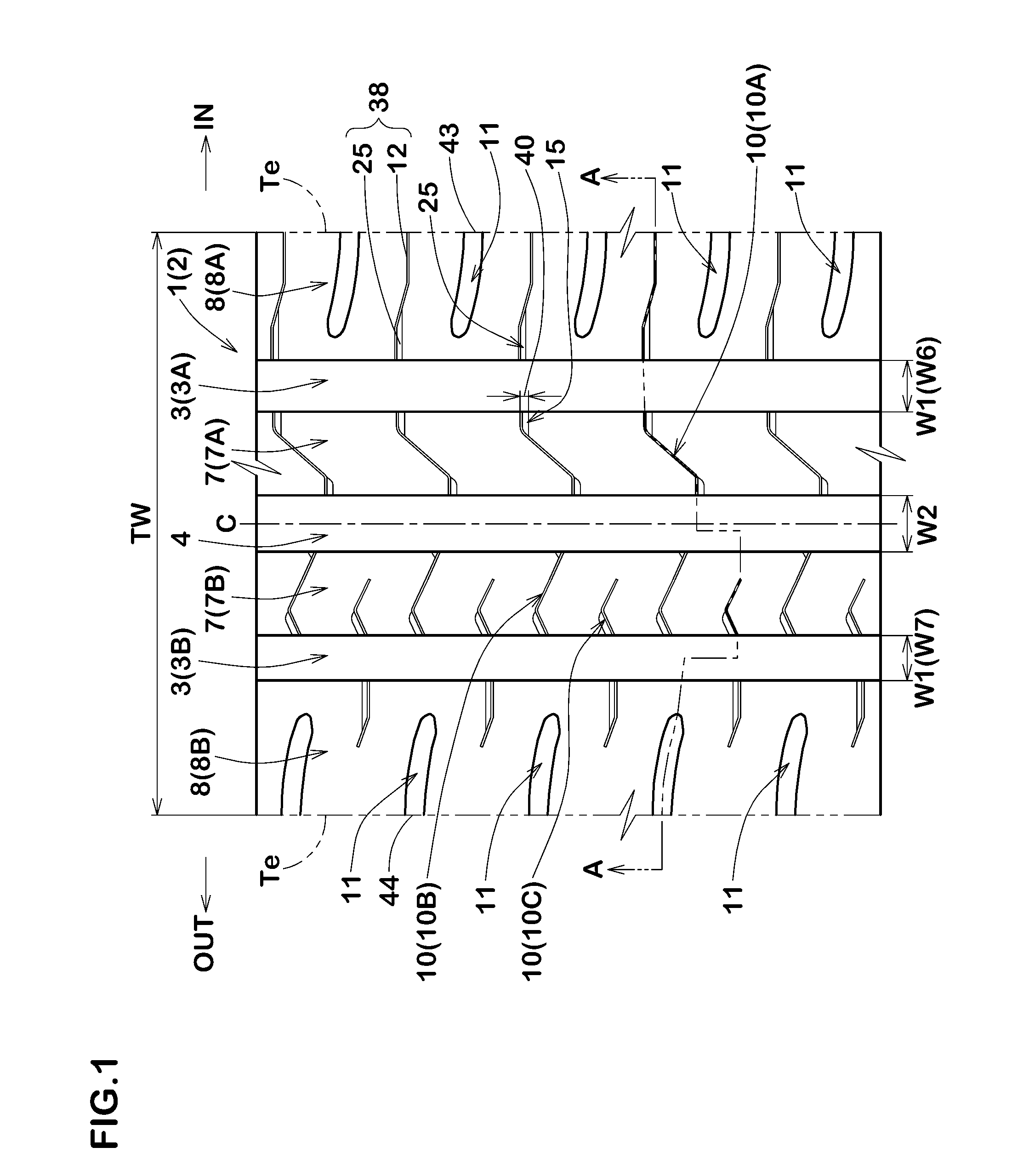
[0128]Based on the tread pattern shown in FIG. 1, pneumatic tires of size 195 / 65R15 (rim size: 15×6J, tire pressure: 230 kPa) having specifications listed in Table 1 were experimentally manufactured and tested for the steering stability on dry roads, wet performance and noise performance.

[0129]In the pneumatic tire as comparative example 1, each middle narrow groove 10 was formed by the sipe-like narrow portion only, namely, the wide portion was omitted as shown in FIG. 10.

[0130]In the pneumatic tire as comparative example 2, each middle narrow groove 10 was entirely provided with a groove width of more than 2 mm and the wide portion was omitted as shown in FIG. 11.

[0131]The test tires were mounted on all wheels of a 2400 cc front-wheel-drive passenger car, and a test driver evaluated the steering stability during running on an asphalt-paved circuit course.

[0132]The results are indicated in Table 1 by an index based on comparative example 1 being 100, wherein the larger the index nu...


PUM


Abstract

A pneumatic tire comprises a tread portion 2 provided with two shoulder main grooves 3, a crown main grooves 4, two shoulder land zones 8, and two middle land zones 7. The shoulder land zones 8 are each provided with shoulder lateral grooves 11. The middle land zones 7 are each provided with middle narrow grooves 10. Each of the middle narrow grooves 10 comprises a sipe-like narrow portion 12 whose groove width is less than 2 mm, and a wide portion 14 whose groove width is not less than 2 mm. The wide portion 14 includes an axially outer wide portion 15 formed at the axially outer end of the middle narrow groove 10.

Description

TECHNICAL FIELD[0001]The present invention relates to a pneumatic tire, more particularly to a tread pattern capable of improving wet performance and steering stability on dry roads well balancedly.BACKGROUND ART[0002]In the following patent document 1, for example, there is disclosed a pneumatic tire whose tread portion is provided in middle land zones with narrow grooves.[0003]Such narrow grooves may serve a function in discharging water in part, while maintaining the rigidity of the middle land zones. In the middle narrow groove of the patent document 1, however, a small groove width of less than 2 mm continues along the length of the groove. Therefore, in the ground contacting patch of the tire, the opposite walls of the narrow groove tend to contact with each other in their substantially whole area. Accordingly, the narrow grooves can not serve for drainage, and aquaplaning phenomenon is liable to occur when running on wet roads at high speed. Thus, in order to satisfy both of ...

Claims


Application Information

Patent Timeline
Patent Type & Authority Applications(United States)
IPC IPC(8): B60C11/03B60C11/12
CPCB60C11/0327B60C11/1272B60C2011/0334B60C2011/0344B60C2011/0365B60C11/1236B60C11/13B60C11/0306B60C2011/036B60C11/125B60C2011/0381B60C2011/0395B60C11/1281B60C11/1376
Inventor TAKEMOTO, YOSHIAKI
Owner SUMITOMO RUBBER IND LTD
Why Eureka
Try Eureka