A solids injection lance

a technology of solids injection and lance, which is applied in the direction of furnace monitoring devices, charge manipulation, furnaces, etc., to achieve the effect of reducing risks and safety concerns

Active Publication Date: 2016-06-02
TATA STEEL
View PDF1 Cites 3 Cited by
  • Summary
  • Abstract
  • Description
  • Claims
  • Application Information

AI Technical Summary

Benefits of technology

[0023]The solids injection lance of the present invention minimises the risks and safety concerns arising from abrasive wear of ...

Problems solved by technology

In this instance, the purpose of the puncture detection system is to detect a puncture before ...

Method used


Image

  • A solids injection lance
  • A solids injection lance
  • A solids injection lance

Examples


Embodiment Construction

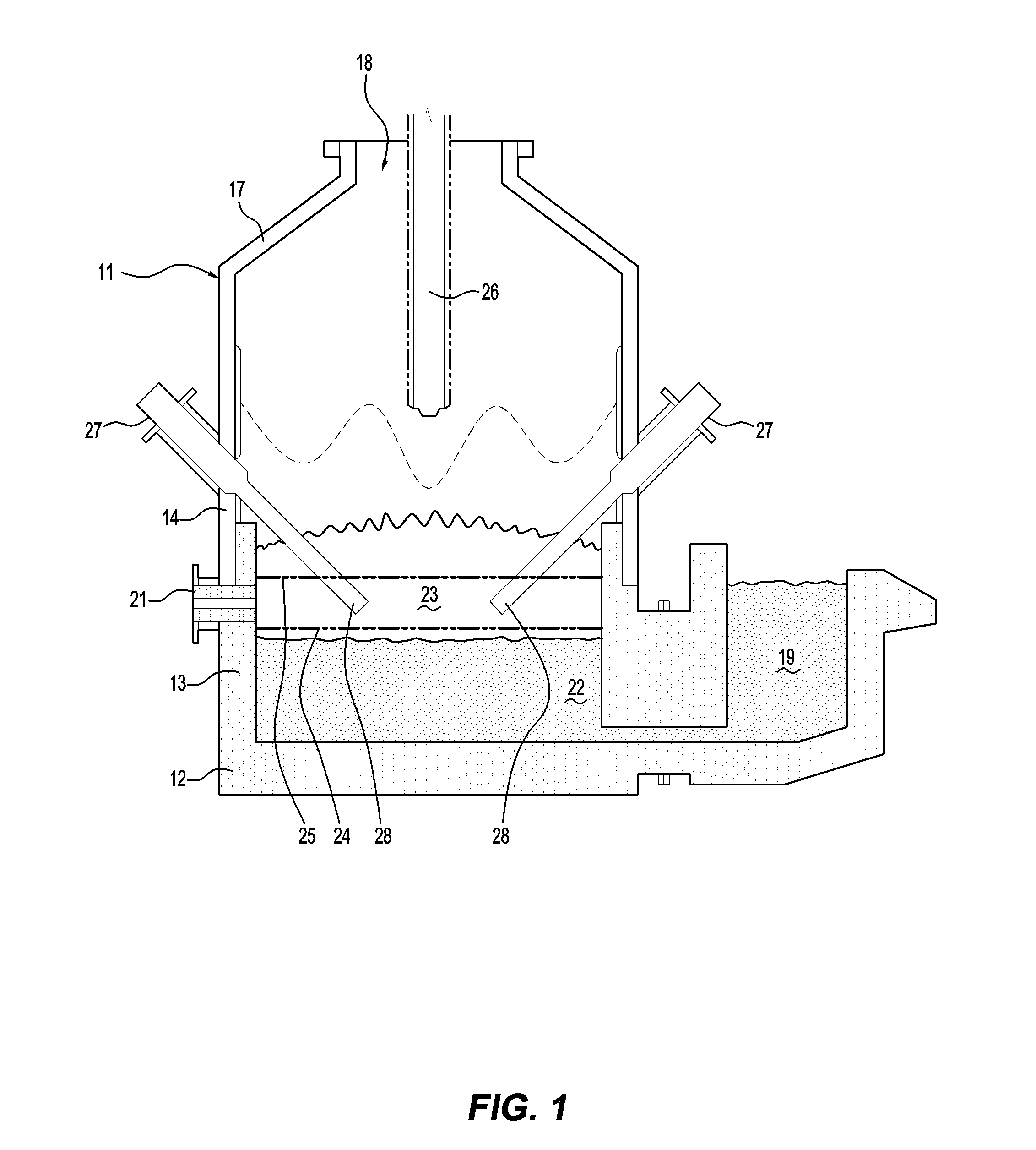
[0084]FIG. 1 shows a direct smelting vessel 11 that is suitable particularly for carrying out the HIsmelt process as described by way of example in International patent application PCT / AU96 / 00197 (WO 1996 / 031627) in the name of the applicant. The vessel 11 forms part of a direct smelting plant (not shown) that includes apparatus for storing and supplying feed materials to the vessel 11 and for handling / processing molten metal, slag and off-gas discharged from the vessel 11.

[0085]The following description is in the context of smelting iron ore fines to produce molten iron in accordance with the HIsmelt process.

[0086]It will be appreciated that the present invention is applicable to smelting any metalliferous material, including ores, partly reduced ores, and metal-containing waste streams via any suitable molten bath-based direct smelting process and is not confined to the HIsmelt process. It will also be appreciated that the ores can be in the form of iron ore fines.

[0087]The vessel...


PUM

PropertyMeasurementUnit
Depthaaaaaaaaaa
Pressureaaaaaaaaaa
Lengthaaaaaaaaaa

Abstract

A solids injection lance includes (a) a tube that defines a passageway for solid feed material to be injected through the tube and has an inlet for solid material at a rear end and an outlet for discharging solid material at a forward end of the tube and (b) a puncture detection system for detecting a puncture in the solids injection tube.

Description

TECHNICAL FIELD[0001]The present invention relates to a lance for injecting solid material into a vessel, such as a molten bath-based direct smelting vessel for producing molten metal, such as iron.[0002]The present invention also relates to a process and apparatus for smelting a metalliferous material, such as an iron-containing material, such as an iron ore, and producing molten iron.BACKGROUND ART[0003]A known molten bath-based smelting process is generally referred to as the “HIsmelt” process and is described in a considerable number of patents and patent applications in the name of the applicant.[0004]The HIsmelt process is applicable to smelting metalliferous material generally but is associated particularly with producing molten iron from iron ore or another iron-containing material.[0005]In the context of producing molten iron, the HIsmelt process includes the steps of:[0006](a) forming a bath of molten iron and slag in a main chamber of a direct smelting vessel;[0007](b) in...

Claims


Application Information

Patent Timeline
IPC IPC(8): F27D3/18F27D3/00C21C5/46F27D3/16
CPCF27D3/18F27D3/16F27D2003/169C21C5/4606F27D2003/164F27D3/0033C21B7/24C21B7/163C21C5/4673C21C2005/4626F27D2003/168F27D2021/0007
Inventor PILOTE, JACQUESDRY, RODNEY JAMESHUTTON, MICHAEL ANTHONY
Owner TATA STEEL
Why Eureka
Try Eureka