Zoom lens system

a zoom lens and lens body technology, applied in the field of zoom lens systems, can solve the problems of deteriorating optical quality, insufficient brightness, easy deterioration of optical quality, etc., and achieves the effects of fast f-number, superior optical quality, and simple and low-cost mechanical structur

Inactive Publication Date: 2016-06-02
RICOH IMAGING COMPANY
View PDF5 Cites 5 Cited by
  • Summary
  • Abstract
  • Description
  • Claims
  • Application Information

AI Technical Summary

Benefits of technology

[0017]According to the present invention, a zoom lens system having a negative lens group and a positive lens group (two lens groups) is achieved, which utilizes its advantages of having a simple and low-cost mechanical structure, attains a sufficiently fast f-number that is small, and favorably corrects various aberrations such as coma, spherical aberration, astigmatism, field curvature and chromatic aberration, etc., to thereby achieve a superior optical quality.

Problems solved by technology

Furthermore, if attempts are made to achieve a fast zoom lens system having a small f-number, since a zoom lens system having a negative lens group and a positive lens group (two lens groups) lacks design freedom and correction of aberrations (especially correction of coma flare) is difficult so that the optical quality thereof easily deteriorates, a zoom lens system having a negative lens group, a positive lens group, a negative lens group and a positive lens group (four lens groups), which has a high degree of design freedom, is often used.
However, in each of these zoom lens systems, the f-number is only around 3.5 through 4, so that the brightness thereof is insufficient.
Furthermore, large amounts of various aberrations such as coma, spherical aberration, astigmatism, field curvature and chromatic aberration occur, so that there is a problem with the optical quality deteriorating.
Patent Literature 1 aims to collect light by providing a flare-cut diaphragm and moving the flare-cut diaphragm during zooming, however, since correction of aberrations over the entire lens system is insufficient in the first place, the flare-cut diaphragm does not function very effectively with respect to the correction of coma aberration.

Method used


Image

  • Zoom lens system
  • Zoom lens system
  • Zoom lens system

Examples


numerical embodiment 1

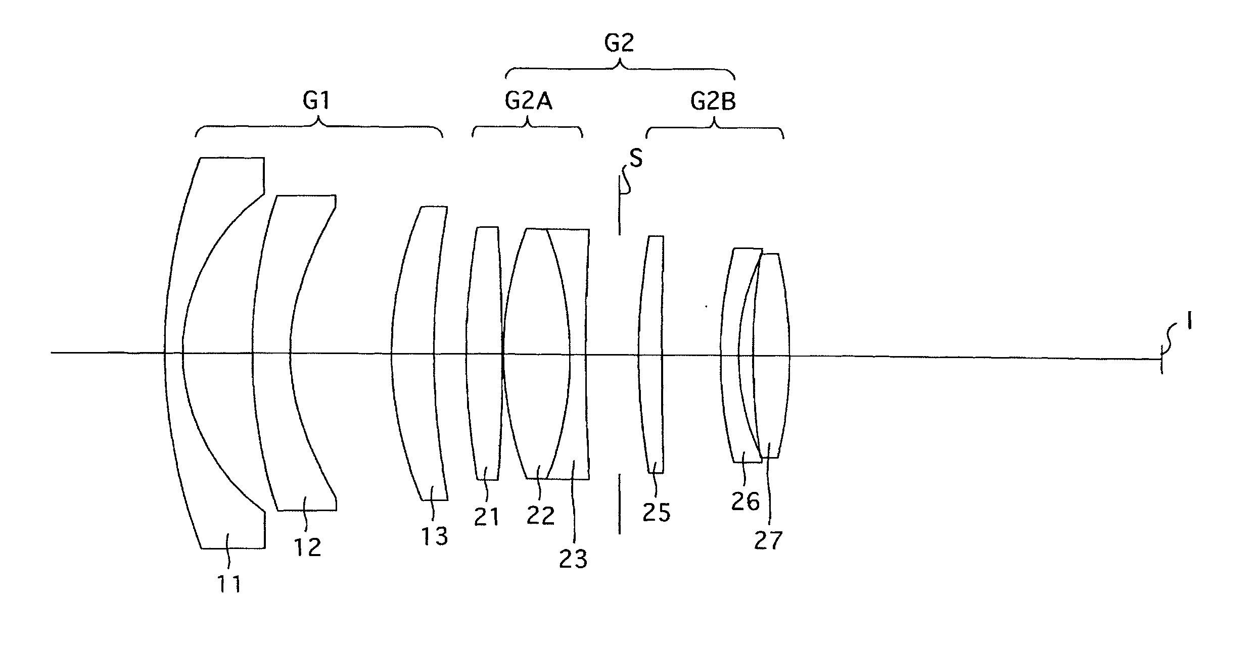
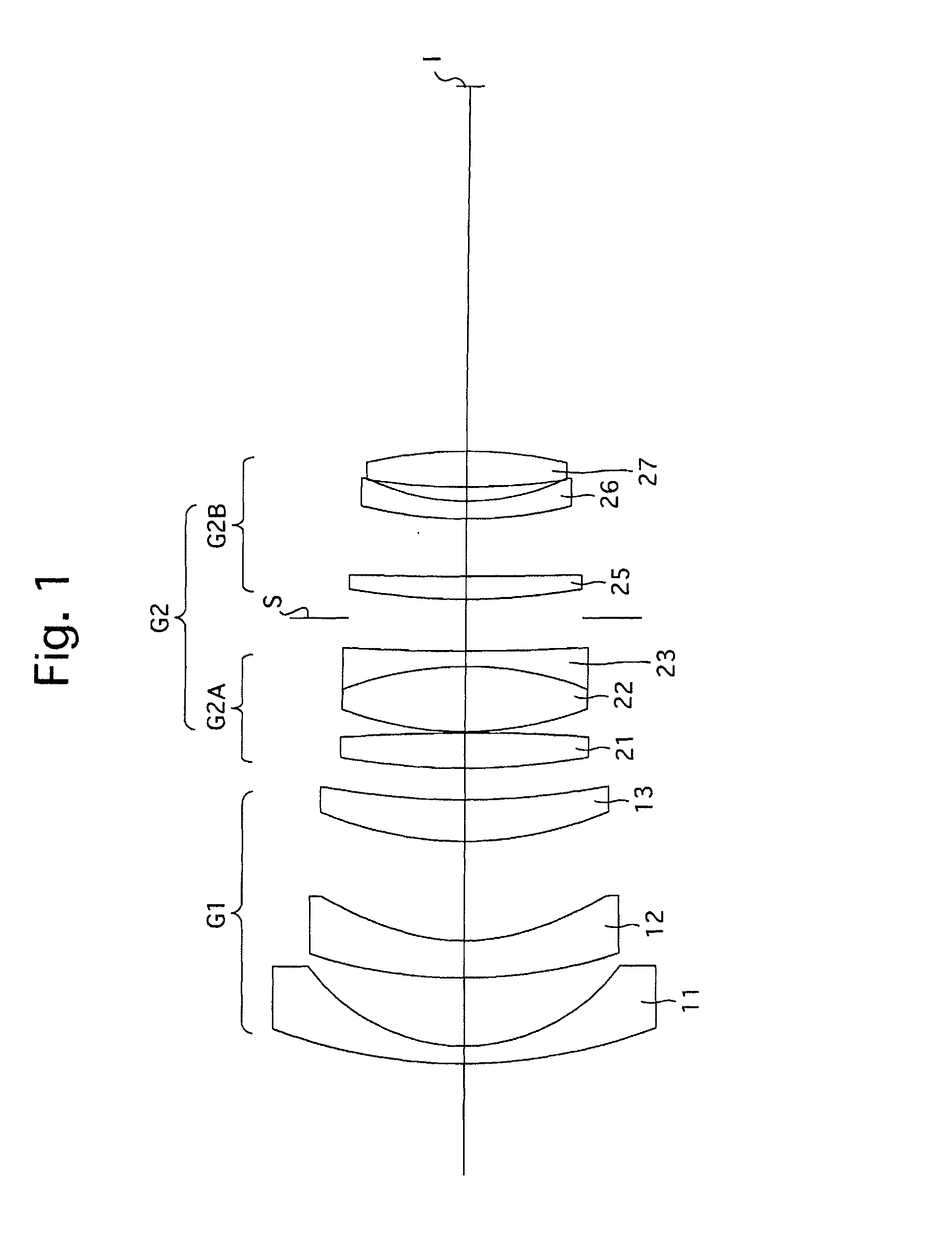
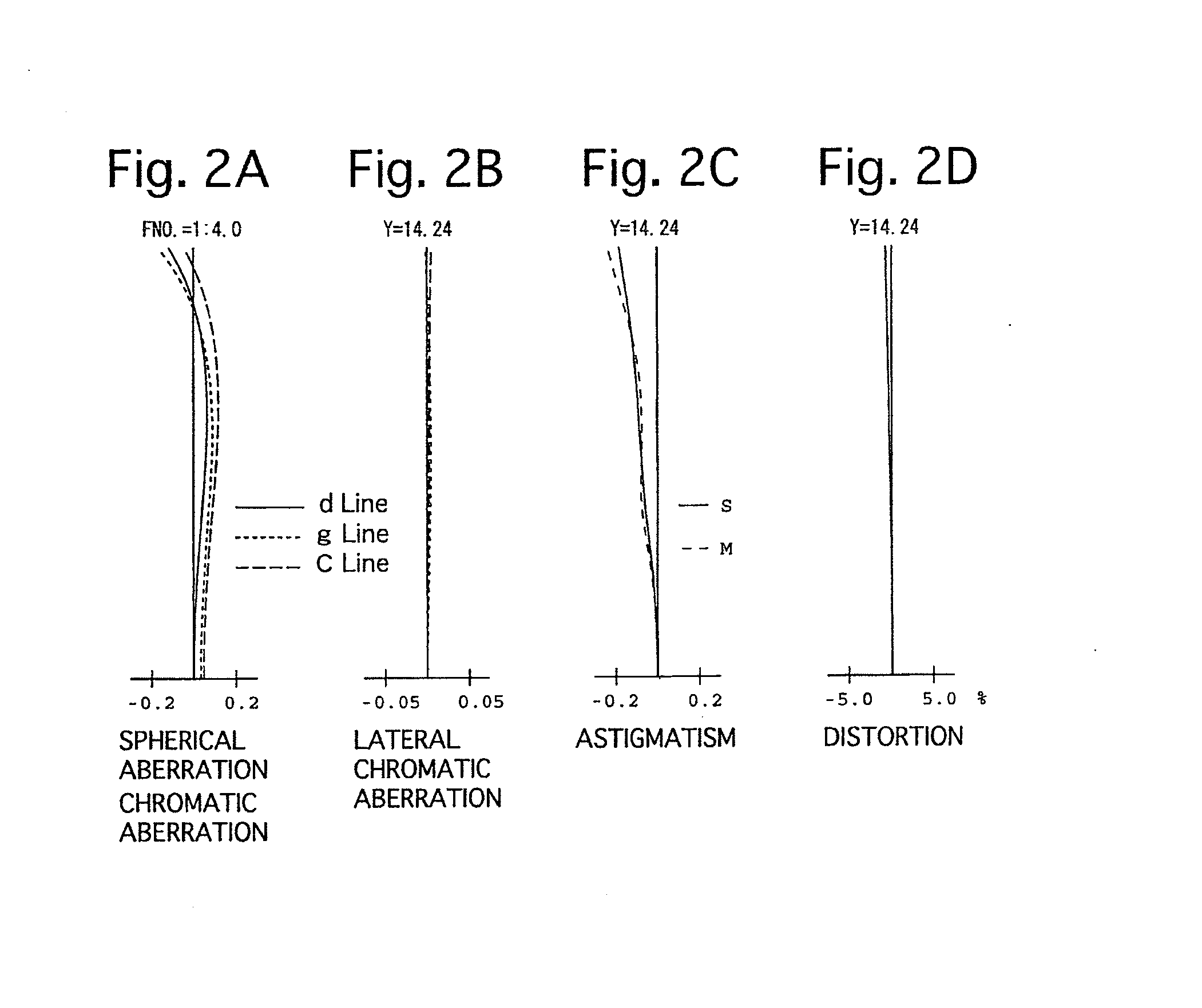
[0099]FIGS. 1 through 6 and Tables 1 through 4 show a first numerical embodiment of the zoom lens system according to the present invention. FIG. 1 shows the lens arrangement at the long focal length extremity when focused on an object at infinity, FIG. 2 shows the various aberrations thereof, FIG. 3 shows the lateral aberrations thereof; FIG. 4 shows the lens arrangement at the short focal length extremity when focused on an object at infinity, FIG. 5 shows the various aberrations thereof, and FIG. 6 shows the lateral aberrations thereof. Table 1 shows the lens surface data, Table 2 shows the aspherical surface data, Table 3 shows various data of the zoom lens system, and Table 4 shows various data of the lens groups.

[0100]The zoom lens system of the first numerical embodiment is configured of a negative first lens group G1 and a positive second lens group G2, in that order from the object side.

[0101]The first lens group G1 is configured of a negative meniscus lens element 11 havin...

numerical embodiment 2

[0105]FIGS. 7 through 12 and Tables 5 through 8 show a second numerical embodiment of the zoom lens system according to the present invention. FIG. 7 shows the lens arrangement at the long focal length extremity when focused on an object at infinity, FIG. 8 shows the various aberrations thereof, FIG. 9 shows the lateral aberrations thereof; FIG. 10 shows the lens arrangement at the short focal length extremity when focused on an object at infinity, FIG. 11 shows the various aberrations thereof, and FIG. 12 shows the lateral aberrations thereof. Table 5 shows the lens surface data, Table 6 shows the aspherical surface data, Table 7 shows various data of the zoom lens system, and Table 8 shows various data of the lens groups.

[0106]The lens arrangement of the second numerical embodiment is the same as that of the first numerical embodiment.

TABLE 5SURFACE DATASurf. No.RdN(d)ν(d) 149.7781.5661.7413153.5 216.6205.824 343.0443.0221.6890052.8 4*19.2688.658 533.5492.9761.7449827.2 675.431d6 ...

numerical embodiment 3

[0107]FIGS. 13 through 18 and Tables 9 through 12 show a third numerical embodiment of the zoom lens system according to the present invention. FIG. 13 shows the lens arrangement at the long focal length extremity when focused on an object at infinity, FIG. 14 shows the various aberrations thereof, FIG. 15 shows the lateral aberrations thereof; FIG. 16 shows the lens arrangement at the short focal length extremity when focused on an object at infinity, FIG. 17 shows the various aberrations thereof, and FIG. 18 shows the lateral aberrations thereof. Table 9 shows the lens surface data, Table 10 shows the aspherical surface data, Table 11 shows various data of the zoom lens system, and Table 12 shows various data of the lens groups.

[0108]The lens arrangement of the third numerical embodiment is the same as that of the first numerical embodiment except for the following features:

[0109](1) The first sub-lens group G2A is configured of a biconvex positive lens element 21′, a positive men...


PUM


Abstract

A zoom lens system includes a negative first lens group and a positive second lens group, in that order from the object side, wherein during zooming from the short focal length extremity to the long focal length extremity, the distance between the first lens group and the second lens group decreases. The second lens group includes a positive first sub-lens group, an aperture diaphragm, and a positive second sub-lens group, in that order from the object side. The following condition (1) is satisfied:
0.65<f2A/f2B<1.0  (1),
wherein f2A designates the focal length of the first sub-lens group, and f2B designates the focal length of the second sub-lens group.

Description

TECHNICAL FIELD[0001]The present invention relates to a zoom lens system that includes a standard range through to an intermediate telephoto range.BACKGROUND ART[0002]Conventionally, a zoom lens system having a negative lens group, a positive lens group, a negative lens group and a positive lens group (four lens groups), and a zoom lens system having a negative lens group and a positive lens group (two lens groups) have been used as zoom lens systems that include a standard range through to an intermediate telephoto range. Generally, although a zoom lens system having a negative lens group, a positive lens group, a negative lens group and a positive lens group (four lens groups) has the beneficial features of having a high freedom of design and being advantageous for correcting aberrations, since the there are a large number of lens groups (lens elements), such a zoom lens system has the disadvantage of the mechanical structure therefor becoming large and complicated; and although a...

Claims


Application Information

Patent Timeline
Patent Type & Authority Applications(United States)
IPC IPC(8): G02B15/177G02B13/18G02B27/00
CPCG02B15/177G02B13/18G02B27/0025G02B15/20G02B15/143507
Inventor OSHISHI, TAKAHIKO
Owner RICOH IMAGING COMPANY
Why Eureka
Try Eureka