Zoom lens system

a zoom lens and lens body technology, applied in the field of zoom lens systems, can solve the problems of deteriorating optical quality, reducing the quantity of peripheral light at the long focal length extremity, increasing weight and complexity, and affecting the quality of optical reproduction, so as to achieve favorable correction of various aberrations and superior optical quality

Active Publication Date: 2017-05-09
RICOH IMAGING COMPANY
View PDF18 Cites 0 Cited by
  • Summary
  • Abstract
  • Description
  • Claims
  • Application Information

AI Technical Summary

Benefits of technology

[0034]According to the present invention, a zoom lens system is provided, which has a fast f-number and favorably corrects various aberrations so that a superior optical quality is achieved.

Problems solved by technology

However, in a so-called ultra telephoto zoom lens system in which the focal length at the long focal length extremity exceeds 400 mm, there is a tendency for axial chromatic aberration, lateral chromatic aberration and spherical aberration to increase, thereby deteriorating the optical quality.
Furthermore, in the case where a telephoto zoom lens system is used in an interchangeable lens camera of a digital SLR camera, since the lens diameter of the rear lens group cannot be enlarged due to mount restrictions, the quantity of peripheral light at the long focal length extremity decreases.
Accordingly, the entire mechanism, which includes a zooming mechanism and a focusing mechanism, becomes enlarged, has an increased weight and increased complexity.
Furthermore, in the zoom lens system of Patent Literature No. 1, a large amount of spherical aberration and field curvature occur during focusing, thereby deteriorating the optical quality.
However, in the zoom lens system of Patent Literature No. 2, the entire mechanism including a zooming mechanism becomes enlarged, has an increased weight, increased complexity, and a large amount of spherical aberration occurs at the long focal length extremity, thereby deteriorating the optical quality.
In the zoom lens system of Patent Literature No. 3, the focal length at the long focal length extremity is 490 mm (which is long), however, the f-number is 6.25 (which is slow) at the long focal length extremity, and a large amount of axial chromatic aberration occurs at the long focal length extremity, thereby deteriorating the optical quality.
Furthermore, in the zoom lens system of Patent Literature No. 3, the second lens group is stationary relative to the image plane during zooming, however, since the diaphragm is moved as an independent group in the optical axis direction, this results in five independent groups being moved in the optical axis direction, and the entire mechanism, including the zooming mechanism, becoming large, having an increased weight and increased complexity.
Furthermore, although the zoom lens system of Patent Literature No. 3 utilizes a front-focusing method, in which the first lens group is moved in the optical axis direction during focusing, since the diameter and weight of the first lens group are large, this zoom lens system is not suitable for autofocusing.
Although the zoom lens system in Patent Literature No. 4 has a focal length of 485 mm (which is long) at the long focal length extremity and the f-number is 5.8 (which is somewhat fast), a large amount of chromatic aberration occurs at the long focal length extremity, thereby deteriorating the optical quality.
Furthermore, although the zoom lens system of the Patent Literature No. 4 utilizes a rear-focusing method, in which the fifth lens group is moved in the optical axis direction during focusing, large amounts of spherical aberration and field curvature occur, thereby deteriorating the optical quality.

Method used


Image

  • Zoom lens system
  • Zoom lens system
  • Zoom lens system

Examples


embodiment 1

[0131][Numerical Embodiment 1]

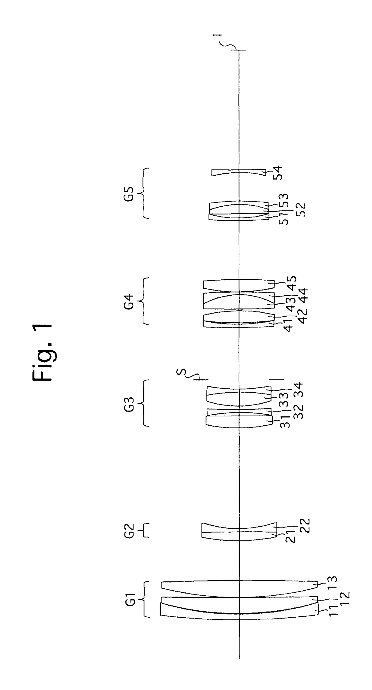
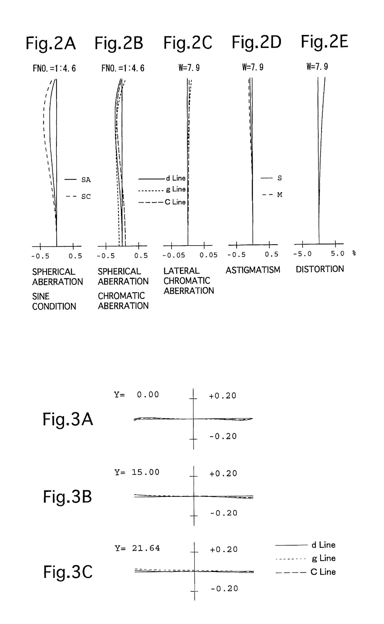
[0132]FIGS. 1 through 6C and Tables 1 through 3 show a first numerical embodiment of a zoom lens system according to the present invention. FIG. 1 is a lens arrangement of the zoom lens system when focused on an object at infinity at the short focal length extremity; FIGS. 2A, 2B, 2C, 2D and 2E show various aberrations that occurred therein; FIGS. 3A, 3B and 3C show lateral aberrations that occurred therein; FIG. 4 is a lens arrangement of the zoom lens system when focused on an object at infinity at the long focal length extremity; FIGS. 5A, 5B, 5C, 5D and 5E show various aberrations that occurred therein; and FIGS. 6A, 6B and 6C show lateral aberrations that occurred therein. Table 1 shows the lens data, Table 2 shows various data, and Table 3 shows lens-group data.

[0133]The zoom lens system of the first numerical embodiment is configured of a positive first lens group G1, a negative second lens group G2, a negative third lens group G3, a positive fou...

embodiment 2

[0142][Numerical Embodiment 2]

[0143]FIGS. 7 through 12C and Tables 4 through 6 show a second numerical embodiment of a zoom lens system according to the present invention. FIG. 7 is a lens arrangement of the zoom lens system when focused on an object at infinity at the short focal length extremity; FIGS. 8A, 8B, 8C, 8D and 8E show various aberrations that occurred therein; FIGS. 9A, 9B and 9C show lateral aberrations that occurred therein; FIG. 10 is a lens arrangement of the zoom lens system when focused on an object at infinity at the long focal length extremity; FIGS. 11A, 11B, 11C, 11D and 11E show various aberrations that occurred therein; and FIGS. 12A, 12B and 12C show lateral aberrations that occurred therein. Table 4 shows the lens data, Table 5 shows various data, and Table 6 shows lens-group data.

[0144]The lens arrangement of the second numerical embodiment differs from the lens arrangement of the first numerical embodiment with respect to the following features:

[0145](1)...

embodiment 3

[0151][Numerical Embodiment 3]

[0152]FIGS. 13 through 18C and Tables 7 through 9 show a third numerical embodiment of a zoom lens system according to the present invention. FIG. 13 is a lens arrangement of the zoom lens system when focused on an object at infinity at the short focal length extremity; FIGS. 14A, 14B, 14C, 14D and 14E show various aberrations that occurred therein; FIGS. 15A, 15B and 15C show lateral aberrations that occurred therein; FIG. 16 is a lens arrangement of the zoom lens system when focused on an object at infinity at the long focal length extremity; FIGS. 17A, 17B, 17C, 17D and 17E show various aberrations that occurred therein; and FIGS. 18A, 18B and 18C show lateral aberrations that occurred therein. Table 7 shows the lens data, Table 8 shows various data, and Table 9 shows lens-group data.

[0153]The lens arrangement of the third numerical embodiment differs from the lens arrangement of the first numerical embodiment with respect to the following features:

[...


PUM


Abstract

A zoom lens system includes a positive first lens group, a negative second lens group, a third lens group including at least one positive lens element or one negative lens element, a positive fourth lens group, and a negative fifth lens group, in that order from the object side. At least the first, second, fourth and fifth lens groups are moved during zooming from the short to long focal length extremities, and the following conditions (1) and (2) are satisfied:−6.5<f1 / f5<−4.6  (1),and−1.2<fw / f3<0.7  (2),wherein f1, f3 and f5 designate the focal lengths of the first and fifth lens groups, respectively, and fw designates the focal length of the entire zoom lens system at the short focal length extremity.

Description

TECHNICAL FIELD[0001]The present invention relates to a zoom lens system including an ultra telescopic range suitable for use in a lens interchangeable camera, such as a digital SLR camera, etc.BACKGROUND ART[0002]A telephoto type of zoom lens configuration having five or more lens groups, in which the power of the first lens group is positive and the power of the rearmost lens group is negative, is often used as a so-called ultra telescopic zoom lens system, in which the focal length at the long focal length extremity exceeds 400 mm (converted to 35 mm format). In order to be applied for autofocusing, this type of ultra telescopic zoom lens system often uses, as a focusing method for focusing on an object at infinity to an object at a close distance, an internal focusing method in which the lens groups between the first lens group and the rearmost lens group are moved in the optical axis direction thereof, or often uses a rear-focusing method in which the rearmost lens group is mov...

Claims


Application Information

Patent Timeline
Patent Type & Authority Patents(United States)
IPC IPC(8): G02B9/60G02B15/163G02B13/00G02B15/17G03B17/56G02B15/173G02B27/00
CPCG02B15/163G02B9/60G02B13/0045G02B15/17G02B15/173G02B27/0025G03B17/565G02B15/145109G02B15/145113
Inventor MURAYAMA, MINORU
Owner RICOH IMAGING COMPANY
Why Eureka
Try Eureka