

Image Pickup Lens And Image Pickup Device
a pickup device and image technology, applied in the field of compact image pickup lenses, can solve the problems of insufficient correction of chromatic aberration, increased size of image pickup devices and image pickup lenses, and inability to achieve high-performance image pickup devices using a higher pixel density solid-state image sensor, etc., to achieve the effect of reducing the angle of refraction, facilitating the securing of the edge thickness of the first lens, and reducing the height of the light beam passing through the first lens
- Summary
- Abstract
- Description
- Claims
- Application Information
AI Technical Summary
Benefits of technology
Problems solved by technology
Method used
Image

Examples
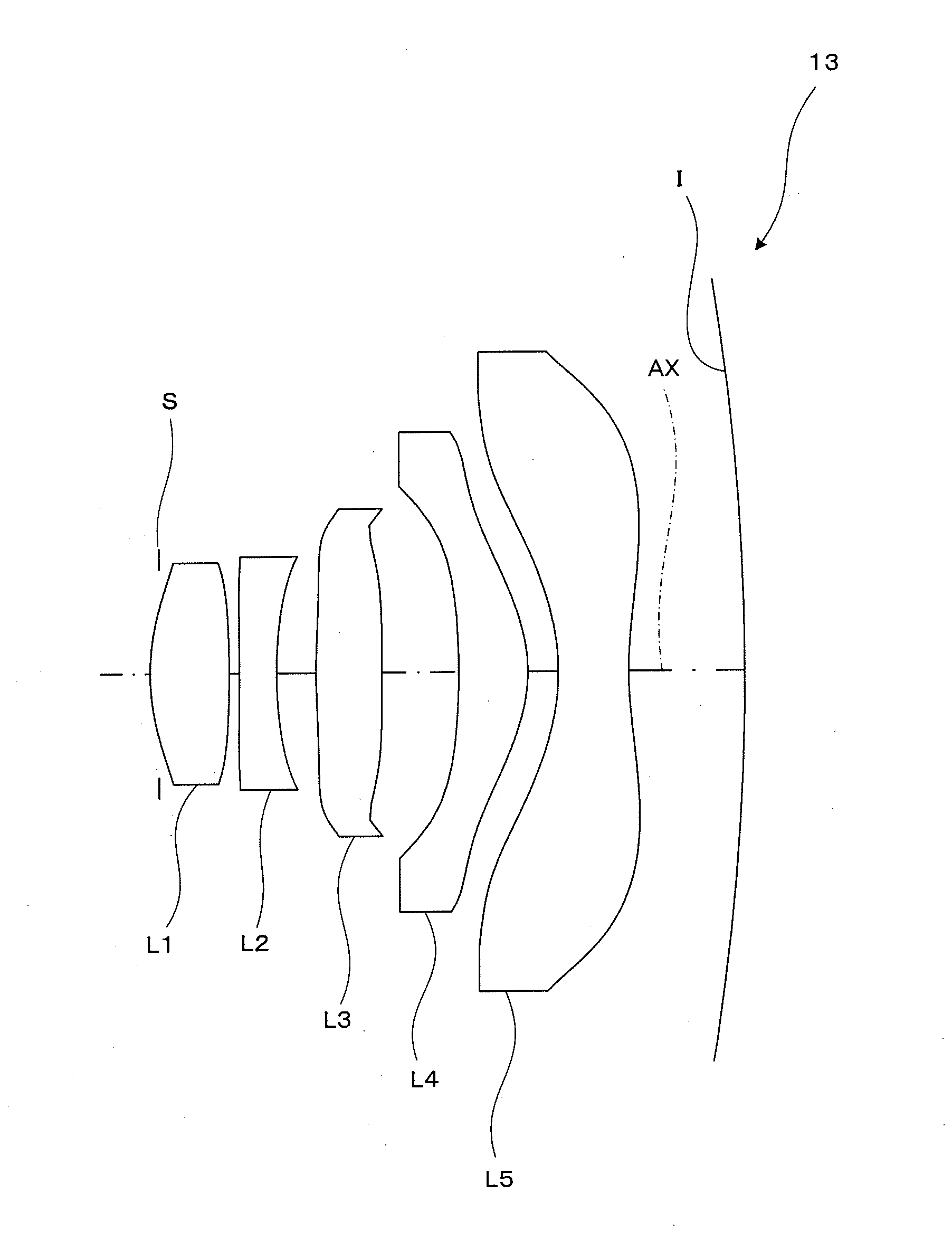
example 1
[0100]The general specifications of an image pickup lens of Example 1 are shown below.
f=4.23 mm
fb=0.64 mm
F=2.8
2Y=7.128 mm
ENTP=0 mm
EXTP=−2.46 mm
H1=−1.55 mm
H2=−3.59 mm
[0101]The data of the lens surfaces of Example 1 is shown in Table 1 below. Note that the STOP means the aperture stop S and the image means the image pickup surface I.
TABLE 1Surface Effective No. R (mm)D (mm)Ndν dradius (mm) 1 (STOP) infinity−0.110.76 2*1.8840.511.5447056.20.76 3*−45.3190.060.82 4*8.2770.231.6347023.90.86 5*2.3110.410.93 6*7.4900.561.5447056.21.38 7*infinity0.481.43 8*−15.0810.481.5447056.21.67 9*−2.7211.122.0110*−2.9980.541.5305055.72.9311*11.8330.623.16IMAGE−15.000
[0102]The aspherical surface coefficients of the lens surfaces of Example 1 are shown in Table 2 below.
TABLE 2Second surfaceK = −0.20272E−01, A4 = 0.21761E−02, A6 = 0.19366E−01, A8 = −0.41471E−01, A10 = 0.98748E−02, A12 = 0.71809E−01, A14 = −0.65602E−01Third surfaceK = 0.30000E+02, A4 = 0.31067E−01, A6 = −0.21519E−01, A8 = 0.78950E−02, A10 =...
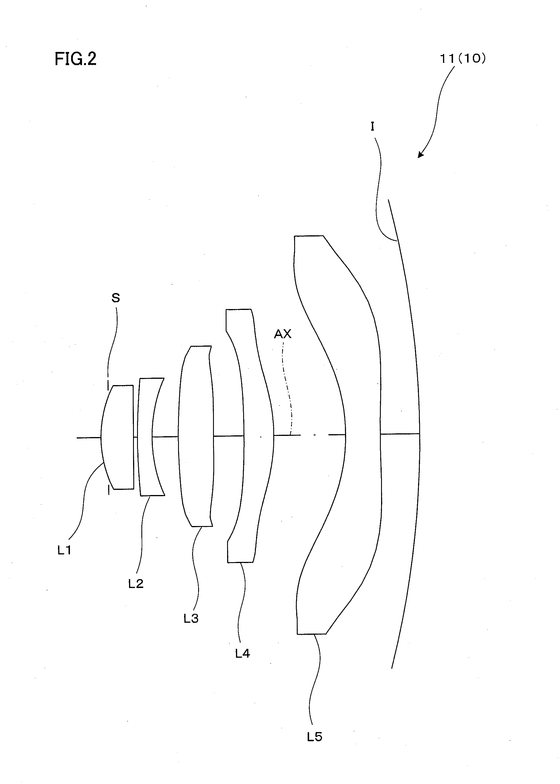
example 2
[0106]The general specifications of an image pickup lens of Example 2 are shown below.
f=3.77 mm
fB=0.78 mm
F=2.22
2Y=5.744 mm
ENTP=0.59 mm
EXTP=−2.47 mm
H1=−0.02 mm
H2=−2.99 mm
[0107]The data of the lens surfaces of Example 2 are shown in Table 4 below.
TABLE 4Surface Effective No. R (mm)D (mm)Ndν dradius (mm) 1infinity0.001.43 2*2.2460.791.5447056.21.19 3*−12.1100.010.90 4 (STOP) infinity0.090.77 5*34.5560.301.6320023.40.79 6*3.1390.250.91 7*6.5350.541.5447056.21.08 8*−12.5820.571.27 9*−3.8760.491.5447056.21.5910*−1.4710.171.7811*9.0650.511.5447056.22.3412*1.7550.372.5613infinity0.151.5163064.12.7914infinity0.772.84IMAGE−10.346
[0108]The aspherical surface coefficients of the lens surfaces of Example 2 are shown in Table 5 below.
[Table 5]
[0109]Second surface
K=−0.45246E+00, A4=−0.10932E−01, A6=0.36384E−02, A8=−0.18871E−01, A10=0.12051E−01, A12=−0.44115E−02, A14=0.10313E−03
[0110]Third surface
K=0.49619E+02, A4=−0.36300E−01, A6=0.10895E+00, A8=−0.19197E+00, A10=0.19397E+00, A12=−0.11550E+00, A14...
example 3
[0122]The general specifications of an image pickup lens of Example 3 are shown below.
f=3.66 mm
fB=0.85 mm
F=2.4
2Y=5.71 mm
ENTP=0 mm
EXTP=−1.81 mm
H1=−1.38 mm
H2=−2.81 mm
[0123]The data of the lens surfaces of Example 3 is shown in Table 7 below.
TABLE 7Surface Effective No. R (mm)D (mm)Ndν dradius (mm) 1 (STOP)infinity−0.060.76 2*1.7200.571.5447056.20.79 3*−9.0540.080.81 4*−33.9240.271.6347023.90.80 5*3.1780.290.85 6*5.5250.481.5447056.21.08 7*infinity0.561.20 8*−6.1350.501.5447056.21.36 9*−1.1340.221.7610*−1.6060.511.5318056.02.0311*2.6650.852.34IMAGE−17.923
[0124]The aspherical surface coefficients of the lens surfaces of Example 3 are shown in Table 8 below.
TABLE 8Second surfaceK = −0.75132E+00, A4 = −0.16106E−01, A6 = −0.74 358E−02, A8 = −0.14477E+00, A10 = 0.18711E+00, A12 = −0.174 76E+00Third surfaceK = 0.30000E+02, A4 = −0.74079E−01, A6 = 0.75740E−01, A8 = −0.25801E+00, A10 = 0.13961E+00Fourth surfaceK = −0.30000E+02, A4 = −0.24 920E−01, A6 = 0.24 525E+0 0, A8 = −0.41253E+00, A10 = 0...
PUM
 Abstract
Description
Claims
Application Information