
Method and apparatus for producing information code

a two-dimensional information and code technology, applied in the field of two-dimensional information code generation methods and apparatuses, can solve problems such as impaired user convenien

Active Publication Date: 2016-06-09
DENSO WAVE INC
View PDF16 Cites 32 Cited by
  • Summary
  • Abstract
  • Description
  • Claims
  • Application Information

AI Technical Summary

Benefits of technology

The patent text describes two embodiments of a program or a generation apparatus that can achieve similar and beneficial effects. The technical effect of this patent is to provide a more efficient and flexible solution for generating a program or apparatus that can perform similar functions to the first embodiment.

Problems solved by technology

By the way, the existing technologies related to information codes lack an idea to freely insert an image at the time of generating a code, although there is a technology of expressing an image (a design or the like) different from a cell shape, in the code region, like JP 5057560 B. Therefore, while a design image or the like can be displayed in the code region, a size or a shape of a displayed image, an overall design of a final code, and the like may not be matched with requirements of a user, and in this regard, convenience of the user is impaired.

Method used


Image

  • Method and apparatus for producing information code
  • Method and apparatus for producing information code
  • Method and apparatus for producing information code

Examples


first embodiment

[0100]Hereinafter, a first embodiment that embodies the present invention will be described with reference to the drawings.

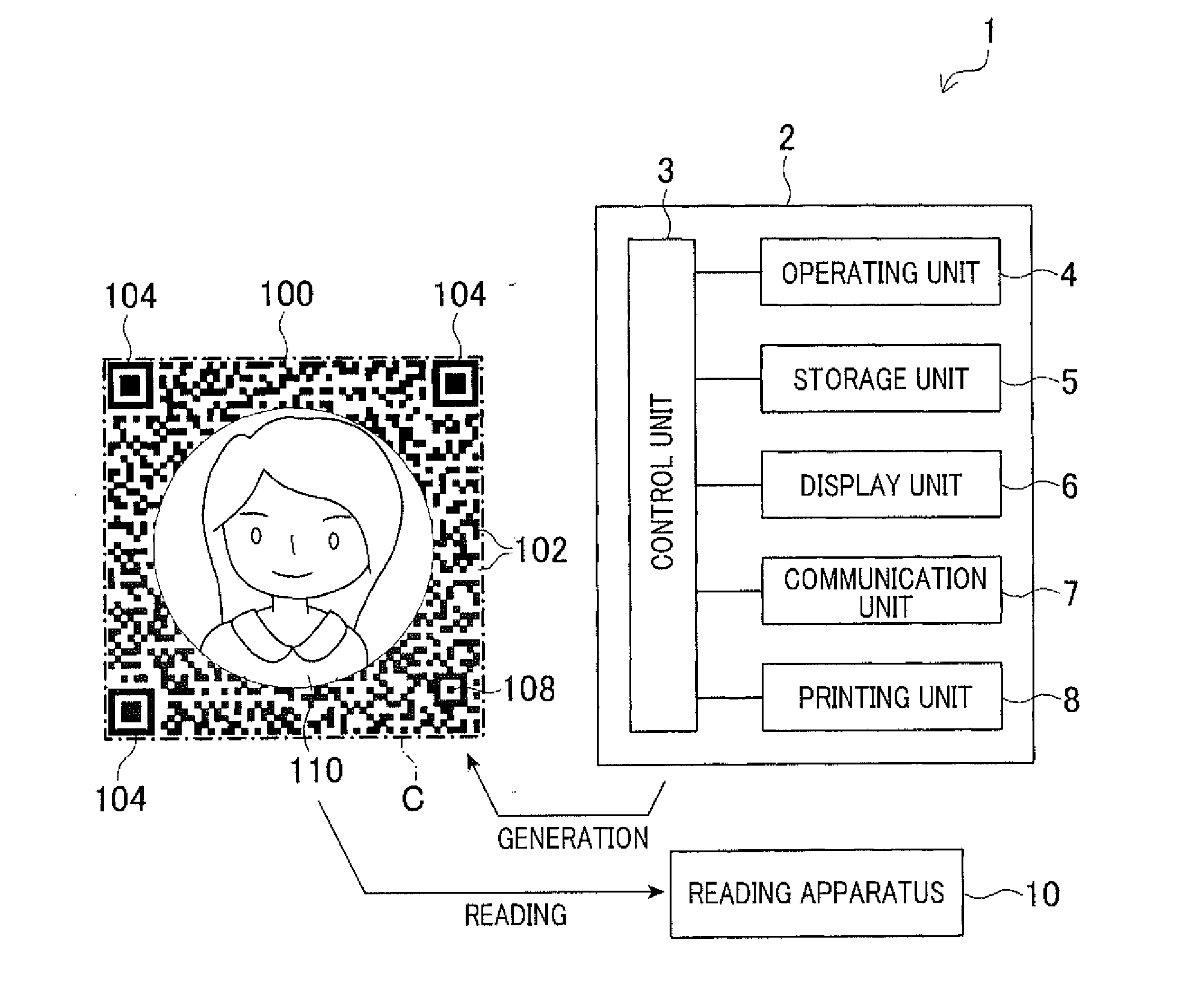
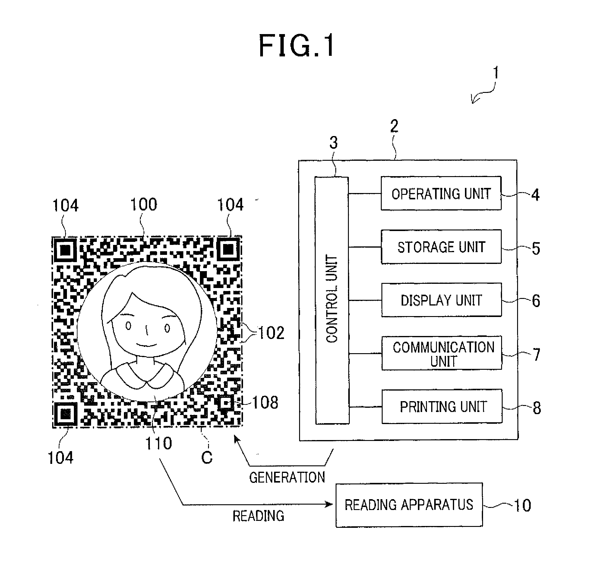
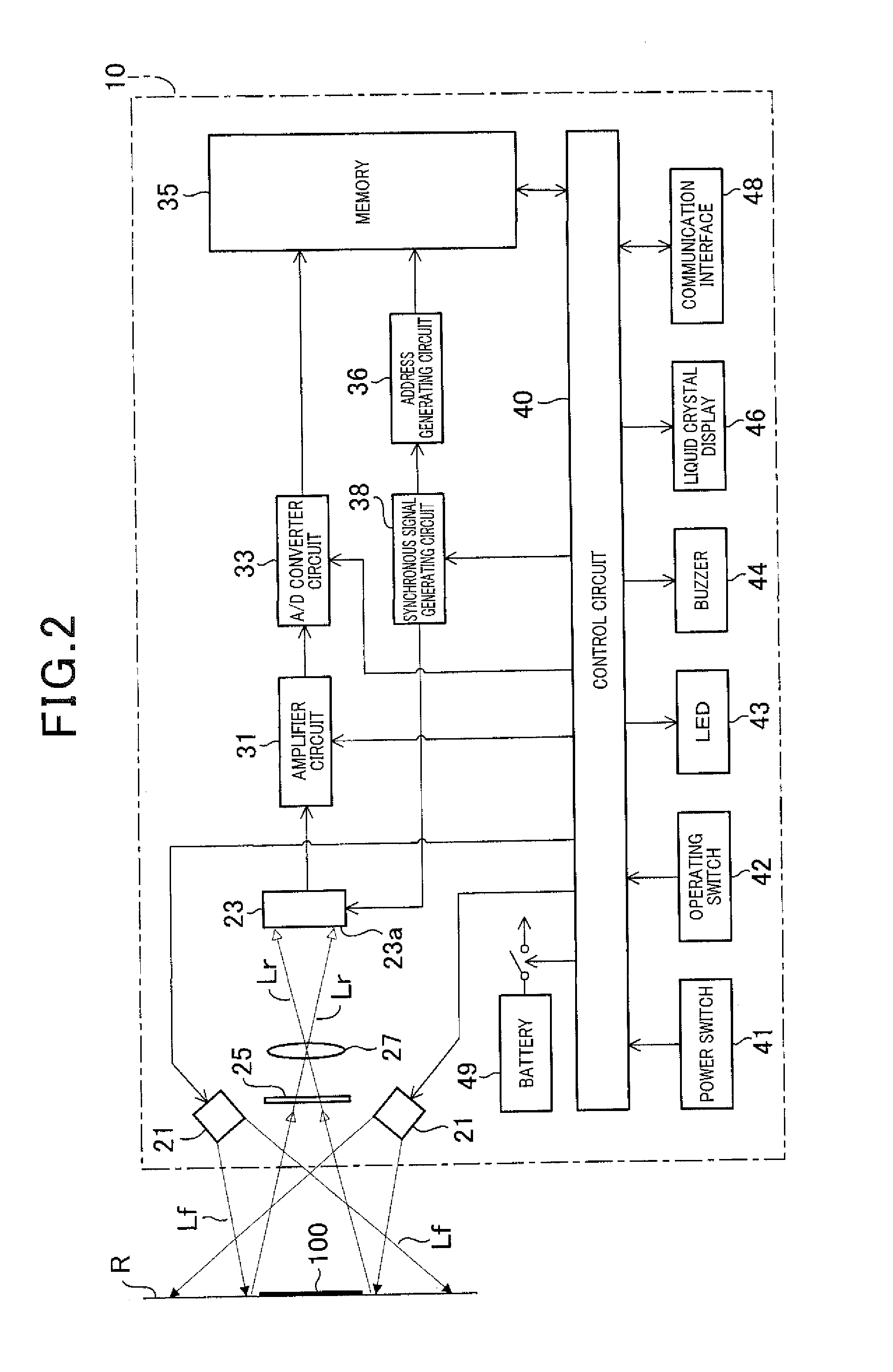
[0101]An information code usage system 1 illustrated in FIG. 1 has a configuration that includes an information code generation (or production) apparatus 2 and an information code reading apparatus 10. The information code generation (or production) apparatus 2 generates (or produces) an information code 100 in which cells are arrayed, the cell serving as a unit of displaying information. The information code reading apparatus 10 reads the information code 100 generated (or produced) by the information code generation (or production) apparatus 2.

[0102](Information Code Generation Apparatus)

[0103]The information code generation apparatus 2 includes, for example, a control unit 3, an operating unit 4, a storage unit 5, a display unit 6, a communication unit 7, and a printing unit 8 (printer). The control unit 3 is configured from a mobile-type information processi...

second embodiment

[0301]Next, a second embodiment will be described.

[0302]An information code usage system according to the second embodiment has the same hardware configuration as that according to the first embodiment. A configuration such as that in FIG. 1 and FIG. 2, described above, is used.

[0303]In the information code usage system according to the second embodiment, the information code generation apparatus 2 (see FIG. 1 and the like) generates an information code 200 such as that in FIG. 35B. In this configuration as well, the specification pattern regions and the data recording region are provided within the code region. The specification pattern region is a region in which a specification pattern (such as a position detection pattern 204) that has a shape prescribed in advance is arranged.

[0304]The data recording region is a region in which data is recorded by a plurality of types of cells. A free space 210 (i.e., canvas region) having a predetermined size that is larger than the size of a ...

third embodiment

[0309]Next, a third embodiment will be described.

[0310]An information code usage system according to the third embodiment also has the same hardware configuration as that according to the first embodiment. A configuration such as that in FIG. 1 and FIG. 2, described above, is used,

[0311]In the information code usage system according to the third embodiment, the information code generation apparatus 2 (see FIG. 1 and the like) generates an information code 300 such as that in FIG. 36B. In this configuration as well, the specification pattern regions and the data recording region are provided within the code region. The specification pattern region is a region in which a specification pattern having a shape prescribed in advance (an L-shaped alignment pattern 304a, and timing cells 304b in which light colored cells and dark colored cells are alternately arranged one cell at a time and forms an L-shaped region along the boundary of the code region) is arranged.

[0312]The data recording ...


PUM


Abstract

A method and an apparatus for generating an information code is provided. In a generation apparatus, after data to be interpreted and data of an image to be displayed are acquired, a code figure that is provided with an image display region is generated and displayed on a display unit. After the code figure is displayed on the display unit in this way, when information designating an arrangement content of the image display region is inputted, an information code is generated. Specifically, an information code is generated in a form in which the image display region is newly arranged based on the arrangement content designated by the input, and a specification pattern region and a region to be interpreted are provided in positions other than that of the image display region. The information code generated in this way is displayed on the display unit.

Description

CROSS-REFERENCE TO RELATED APPLICATIONS[0001]This application is based on and claims the benefit of priority from earlier Japanese Patent Applications No. 2014-206651 filed on Oct. 7, 2014 and No. 2015-191783 filed on Sep. 29, 2015, the descriptions of which are incorporated herein by reference.BACKGROUND[0002]1. Technical Field[0003]The present invention relates to a method and an apparatus for generating information codes, and in particular, to a method and an apparatus for generating a two-dimensional information code such as a QR code (registered trademark) in which an image is incorporated in the code region thereof.[0004]2. Related Art[0005]At present, uses of information codes have been diversified, and technologies of arranging a photograph or a graphic in a code region have been proposed. For example, the technology of JP 5057560 B obtains an inversely converted bit string by inverse transform of a bit string that forms a region read as a single value in a two-dimensional c...

Claims


Application Information

Patent Timeline
Patent Type & Authority Applications(United States)
IPC IPC(8): G06K19/06
CPCG06K19/06037G06K19/06046G06K19/06065
Inventor ITO, KUNIHIKOYOSHIDA, KENICHITANAKA, MASAMIWATABE, MOTOAKIYODA, TAKUYA
Owner DENSO WAVE INC
Learn More