Connector cover and method for manufacturing the same

a technology of connecting rods and connectors, applied in the direction of coatings, other domestic articles, coupling devices, etc., can solve the problem of difficult to obtain constant dimensions, and achieve the effect of suppressing shininess

Inactive Publication Date: 2016-06-09
SUMITOMO WIRING SYST LTD
View PDF0 Cites 0 Cited by
  • Summary
  • Abstract
  • Description
  • Claims
  • Application Information

AI Technical Summary

Benefits of technology

[0016]According to the present invention, it is possible to provide a connector cover amenable to precise control of the outer diameter dimensions and suppression of shininess on its outer face, and a method for manufacturing the same.

Problems solved by technology

Thus, there is a problem in that, although the face on the inner side of the obtained connector cover, that is, the inner surface in contact with the mold is shaped exactly in conformity with the dimensions of the mold, the face on the outer side of the cover, that is, the outer surface has dimensions that vary in accordance with the amount of solution that adheres to the mold.
That is to say, the connector cover obtained according to the method described in JP S60-105118A is problematic in that, although the dimensions on the inner surface side, that is, the inner diameter dimensions are in conformity with the dimensions of the mold, the dimensions on the outer surface side, that is, the outer diameter dimensions depend on the amount of solution that adheres to the mold, and, thus, it is difficult to obtain constant dimensions due to variation in the wall thickness and the like.

Method used


Image

  • Connector cover and method for manufacturing the same
  • Connector cover and method for manufacturing the same
  • Connector cover and method for manufacturing the same

Examples


Embodiment Construction

[0029]Hereinafter, embodiments of the present invention will be described with reference to the drawings.

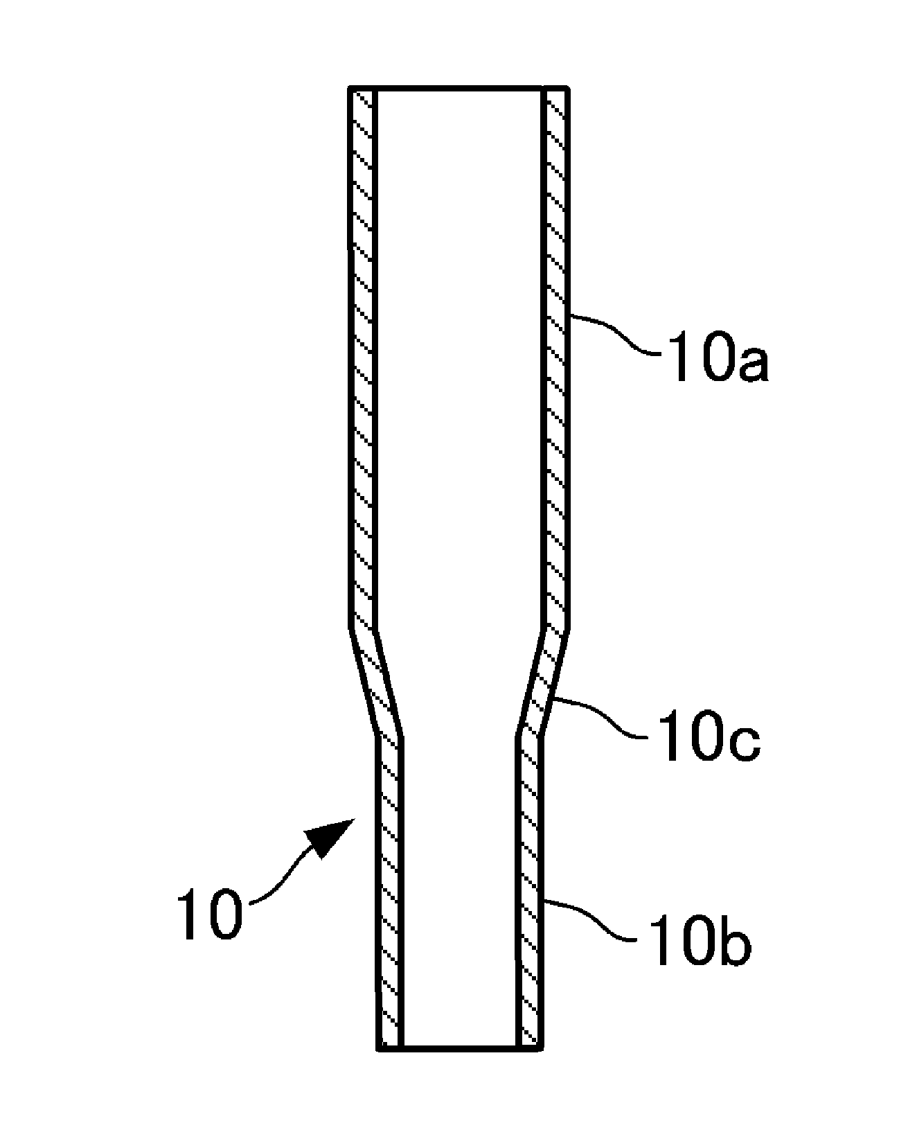
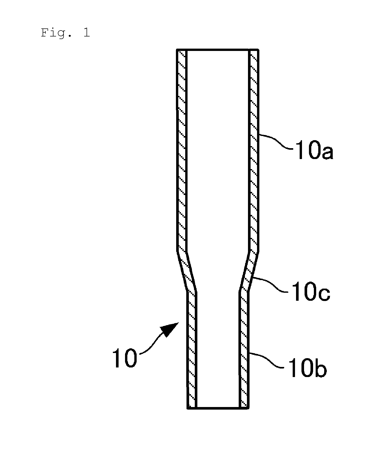
[0030]FIG. 1 shows a connector cover according to this embodiment.

[0031]As shown in FIG. 1, a connector cover 10 has a large-diameter connector covering portion 10a that can cover a connector into which a terminal or terminals connected to ends of an electrical wire bundle in a wire harness (not shown) are inserted and fastened, a small-diameter electrical wire covering portion 10b that can cover the electrical wire bundle, and a coupling portion 10c that continuously couples the connector covering portion 10a and the electrical wire covering portion 10b into one piece.

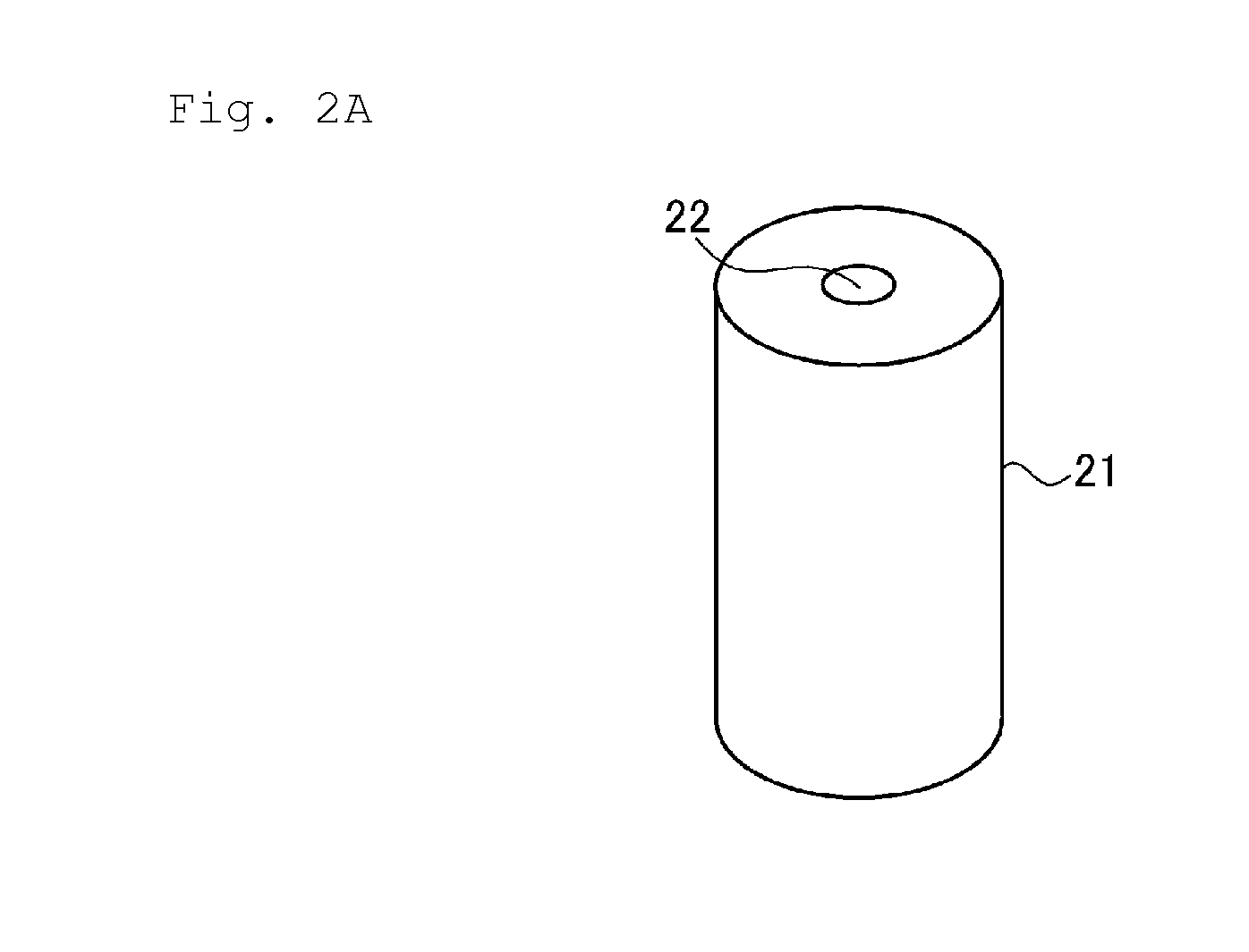
[0032]The connector cover 10 is manufactured using a shaping mold 21, which will be described later, so that the outer diameter dimensions thereof are in conformity with predetermined inner diameter dimensions of a through-hole 22 of the mold 21, and the outer face thereof is a grainy face or a matte face.

[0033]Thi...


PUM

PropertyMeasurementUnit
inner diameteraaaaaaaaaa
diameteraaaaaaaaaa
shapeaaaaaaaaaa

Abstract

In order to provide a connector cover amenable to precise control of the outer diameter dimensions and suppression of shininess on the outer surface thereof, and a method for manufacturing the same, a shaping mold (21) in which a through-hole (22) having a predetermined inner diameter dimension is formed along an immersion direction is immersed in a solution of thermoplastic resin. The shaping mold (21) is pulled up from the solution, and the resin adhering to an inner surface portion of the through-hole (22) of the shaping mold (21) is gelled, so that a precursor (110) is shaped. The precursor (110) is released from the shaping mold (21), and an unnecessary portion (111) of the precursor (110) is cut off. The thus manufactured connector cover (10) that is attachable to a connector into which a terminal connected to ends of an electrical wire bundle in a wire harness is inserted and fastened has an outer diameter dimension in conformity with the inner diameter dimension of the through-hole (22) and has an outer surface that is a matte face or a grainy satin face.

Description

CROSS-REFERENCE TO RELATED APPLICATIONS[0001]This application is the U.S. national stage of PCT / JP2014 / 060047 filed Apr. 7, 2014, which claims priority of Japanese Patent Application 2013-083200 filed Apr. 11, 2013.FIELD OF THE INVENTION[0002]The present invention relates to a connector cover for protecting a connector and the like of a wire harness, and a method for manufacturing the same.BACKGROUND OF THE INVENTION[0003]Conventionally, as a method for manufacturing covers and the like used to protect connectors and terminals of wire harnesses, a method is known that uses a male shaping mold (see Patent Document 1, for example).[0004]Specifically, a pre-heated male shaping mold is immersed in a solution of thermoplastic resin to which a foaming agent has been added, after which the male shaping mold is pulled up in a state where the solution has uniformly adhered to the surface of the male shaping mold, and is heated, so that the adhering solution is gelled and is foamed. Subsequen...

Claims


Application Information

Patent Timeline
Patent Type & Authority Applications(United States)
IPC IPC(8): H01R13/50H01R43/18
CPCH01R43/18H01R13/50B29L2023/00B29C41/02B29C2793/0027B29C2793/009H01R4/70
Inventor ITOU, HITOSHI
Owner SUMITOMO WIRING SYST LTD
Why Eureka
Try Eureka