Fixed shadow belt, fixed shadow device and image formation device

A technology of fixing belt and image, applied in the field of fixing device, image forming device, and fixing belt, can solve the problems of uneven gloss, not considering the reduction range of temperature, difference, etc., and achieve the effect of suppressing uneven gloss

Active Publication Date: 2019-02-15
KONICA MINOLTA INC
View PDF9 Cites 0 Cited by
  • Summary
  • Abstract
  • Description
  • Claims
  • Application Information

AI Technical Summary

Problems solved by technology

[0005] However, in the image forming apparatus described in Patent Document 1, the difference between the region of the fixing belt corresponding to the region of the transfer material on which the image is formed and the region of the fixing belt corresponding to the region of the transfer material not formed on the image is not considered. The temperature of the fixing belt when the temperature of the area decreases by different degrees, or when printing continuously on transfer materials of different sizes
That is, in the image forming apparatus described in Patent Document 1, there is room for improvement in terms of gloss unevenness.

Method used

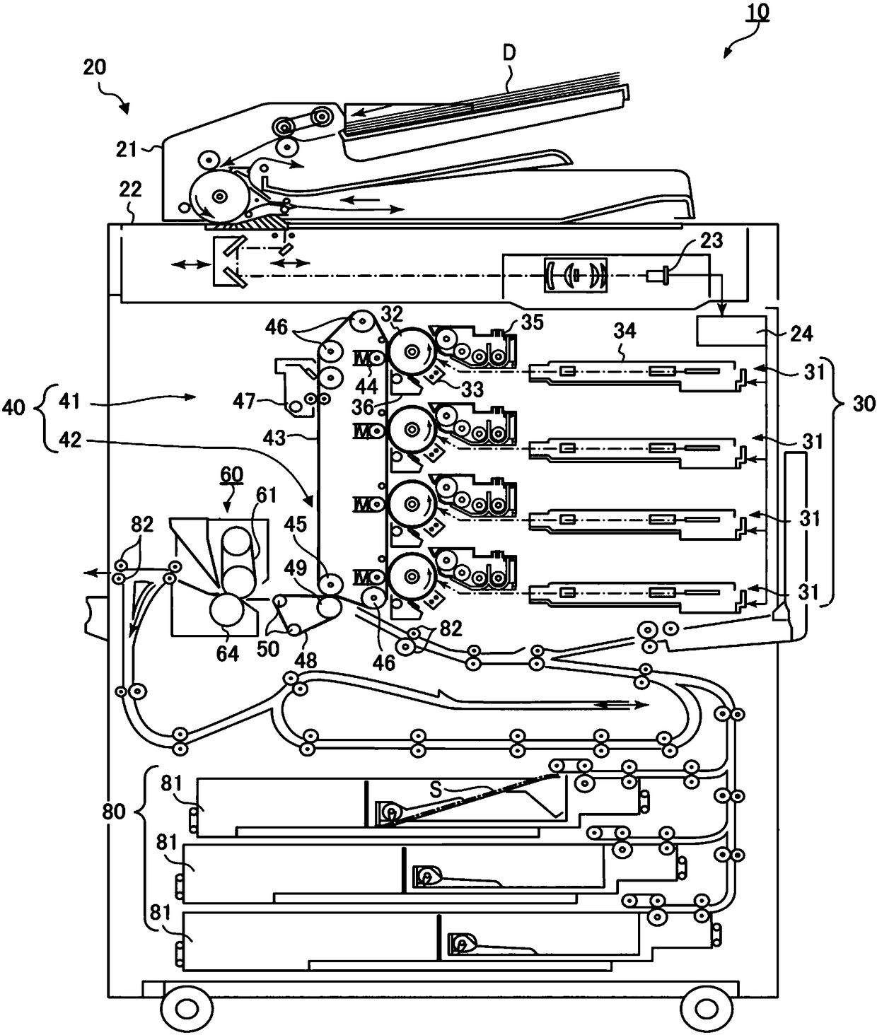
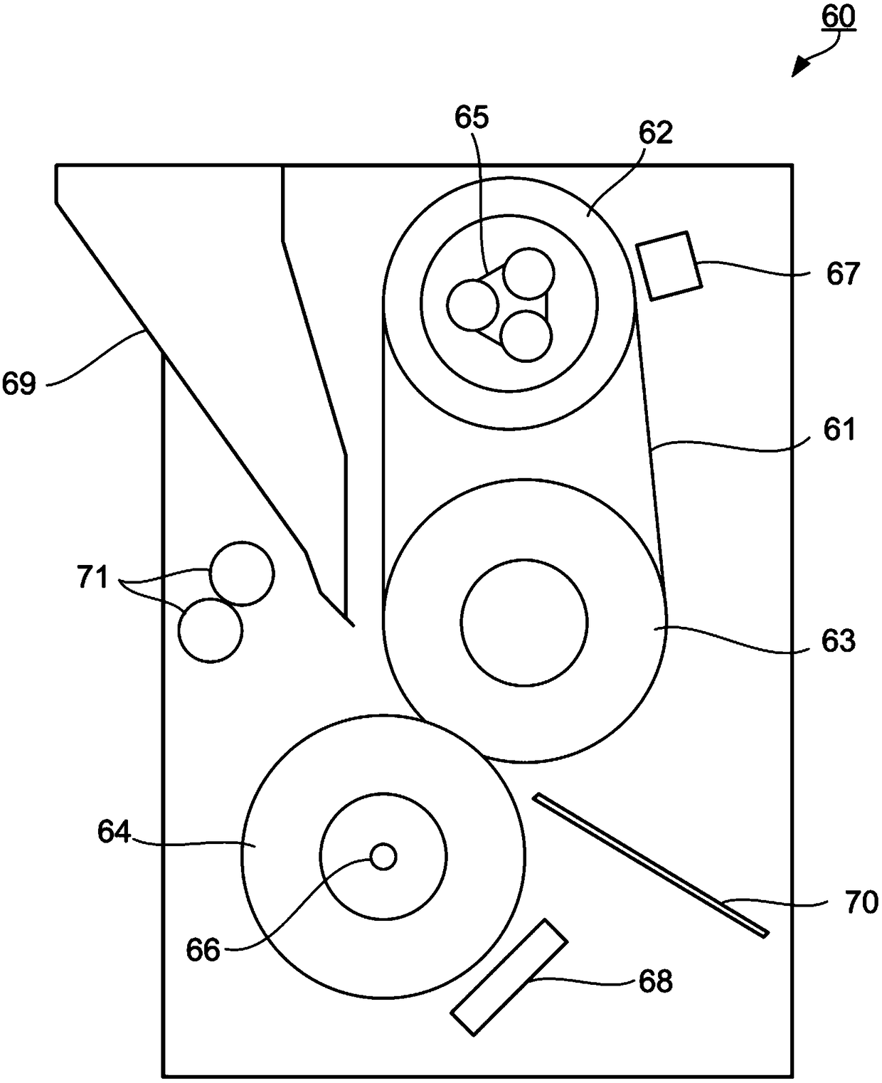
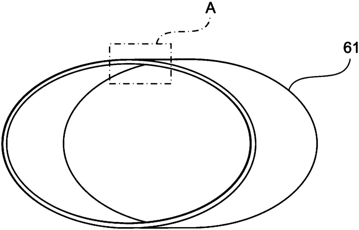

Image

  • Fixed shadow belt, fixed shadow device and image formation device
  • Fixed shadow belt, fixed shadow device and image formation device
  • Fixed shadow belt, fixed shadow device and image formation device

Examples


Embodiment 1

[0106] A cylindrical mandrel made of stainless steel with an outer diameter of 60 mm was closely adhered to the inside of a tape base material made of a thermosetting polyimide resin with an inner diameter of 99 mm, a length of 360 mm, and a thickness of 70 μm. Next, on the outer side of the belt base material, a cylindrical mold holding a PFA tube with a thickness of 30 μm is covered on the inner peripheral surface, so that the mandrel and the cylindrical mold are coaxially held, and a space is formed between the two. cavity. Next, the silicone rubber material A was injected into the cavity, heat-cured, and an elastic layer of the silicone rubber A with a thickness of 200 μm was produced. In this way, the fixing belt 1 was produced in which the belt base material, the elastic layer of silicone rubber A, and the release layer made of PFA were laminated in this order.

[0107] The produced fixing belt 1 was fixed on an aluminum cylinder base, heated from the inside with a halo...

Embodiment 2~6 and comparative example 1~3

[0124] Except for adjusting the type of dimethyl polysiloxane having a vinyl group in the side chain, the mixing ratio of various types, the amount of additives, etc., similar to the production based on silicone rubber A, each with silicone rubber B was produced. Fixing belt 2 with elastic layer, fixing belt 3 with elastic layer made of silicone rubber C, fixing belt 4 with elastic layer made of silicone rubber D, fixing belt 5 with elastic layer made of silicone rubber E, fixing belt with elastic layer made of silicone rubber F The fixing belt 6 with an elastic layer made of silicone rubber G, the fixing belt C1 with an elastic layer made of silicone rubber G, the fixing belt C2 with an elastic layer made of silicone rubber H, and the fixing belt C3 with an elastic layer made of silicone rubber I. In addition, in the same manner as the silicone rubber A, various physical properties of the silicone rubbers B to I were measured. In addition, except that the fixing belts 2 to 6 ...


PUM


Abstract

A fixing belt includes a base layer made of a heat-resistant resin, an elastic layer made of an elastic material, and a releasing layer, which are laminated in this order, and the difference between the maximum value and the minimum value of viscoelastic modulus within a range of 100 to 200° C. is 0.8% or less. Further, the viscoelastic modulus of the fixing belt within the range of 100 to 200° C. is within a range of 50 to 62%.

Description

technical field [0001] The invention relates to a fixing belt, a fixing device and an image forming device. Background technique [0002] Currently, in electrophotographic image forming apparatuses including copiers, laser printers, etc., a heated fixing belt is brought into contact with a transfer material carrying an unfixed toner image, and the toner image is transferred. Fixing device for fixing on the material. As such a fixing device, a device having a fixing belt and two or more rollers including a heating roller and axially supporting the fixing belt is known (for example, refer to Patent Document 1). Since the heat capacity of the fixing belt is relatively small, the performance of fixing the toner image to the transfer material is excellent, which contributes to speeding up image formation. [0003] The fixing device of the image forming apparatus described in Patent Document 1 includes an endless fixing belt, a fixing roller and a heating roller that pivotally s...

Claims


Application Information

Patent Timeline
Patent Type & Authority Patents(China)
IPC IPC(8): G03G15/20
CPCG03G15/2057G03G15/2053G03G2215/2032
Inventor 小贺浩史向山泉植村直子
Owner KONICA MINOLTA INC
Why Eureka
Try Eureka